4. Service Procedures - Replace Components - Suction Feed Bin
128 Morgana DocuMaster MFC - Service Manual
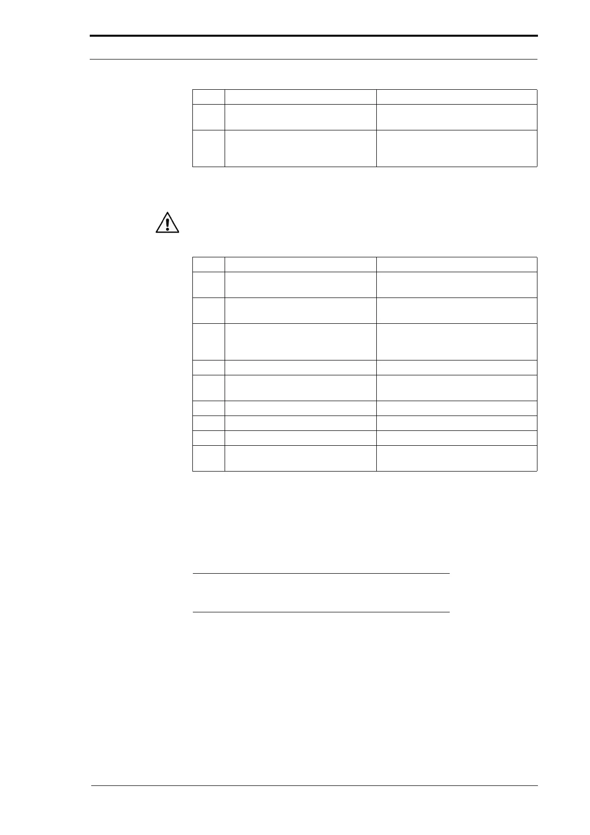
4.8.7.2 Install the Feed Bin Control PCB
Caution: Always wear an anti-static wrist band or earth yourself to the MFC before you
touch a PCB.
Step Action Information
1 Pull out all the retainers on the
sensor sockets.
2 Push the PCB on to the locking
support post
s.
3 Connect the sensor ribbons. Make sure that the metalled side of
th
e ribbon faces away from the
retainer.
4 Connect the component cables.
5 Connect the Data and Power bus
cables.
6 Turn on the MFC.
7 Address the feed bins. (See Section 4.5.5).
8 Initialise the feed bins. (See Section 4.5.6).
9 Do a check of the emitter/sensor
low range ad
justment.
(See Section 4.5.7).
4.8.8 Replace the Emitter/Sensor Assembly
The feed bin emitter and sensor are mounted to the paper guides within the feed bin's
conveyor. To replace the emitter/sensor assembly it is necessary to remove the DRV
module and any feed bins above the one that you must work on.
Note: It is recommended that you connect the replacement
emitter/sensor assembly to the bin control PCB and tested it
before you dismantle the MFC
(see Section 4.4.3).
4 Disconnect the feed bin sensors
ribbons.
Pull up the retainer on the sensor
socket to release the
ribbon.
5 Remove the bin control PCB. Push in the locking tab on each PCB
support post
and pull gently on the
PCB.
Step Action Information