4. Service Procedures - Replace Components - Electrical Cabinet
176 Morgana DocuMaster MFC - Service Manual
Caution: Always make a check that the position of the mode-configuration switches is
correct when you have replaced the
low power stepper drive PCB (see Section 7.3.9).
Tools:
• Anti-static wrist-band and lead
• Screwdriver: Pozidriv No. 2.
Before you start:
• Remove the electrical cabinet cover (See Section 4.2.12).
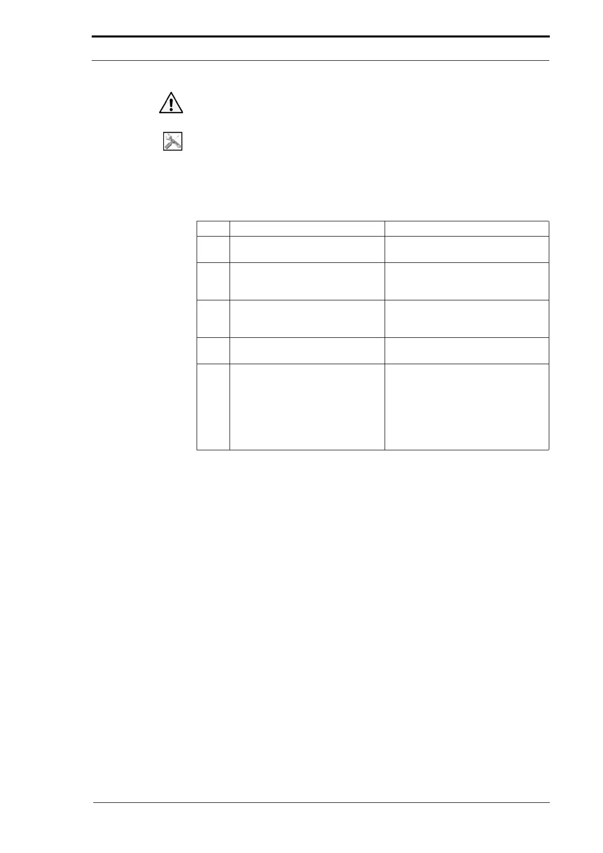
Step Action Information
1 Disconnect the cable connectors
from the low-power stepper PCB.
2 Disconnect the AC power supply
wires from the
low-power stepper
PCB.
3 Remove the four screws that
att
ach the low-power stepper PCB
to the electrical cabinet.
4 Lift the low-power stepper PCB
away from the
electrical cabinet.
5 Install the replacement low-power
stepper PCB.
• Attach the cable connectors to
the dual stepper PCB (see
Section 7.3.9).
• Do a check of the mode
configuration switches and
adjust them as necessary (see
Section 7.3.9).