7. Electrical and Control System - PCBs
224 Morgana DocuMaster MFC - Service Manual
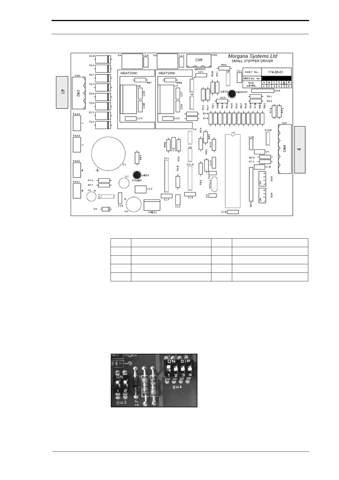
Figure 7.12 Low Power Stepper Motor Drove PCB
Description LED LED Function (LED ON)
CN2 DynaTilt drive stepper motor
CN4 DynaTilt drive control signal
CN5 Sensor input (not used) LED2 Sensor covered
LED1 Power ON
7.3.10 High Power Stepper Motor Drive PCB
The high power stepper motor drive PCB operates the main drive motor.
The low power stepper PCB has two mode configuratio
n switches. The switches must
be set specifically for the type of function that the stepper motor is used for (see Table
below).
Figure 7.13 Mode Configuration Switches