4. Service Procedures - Machine Adjustments and Calibration
70 Morgana DocuMaster MFC - Service Manual
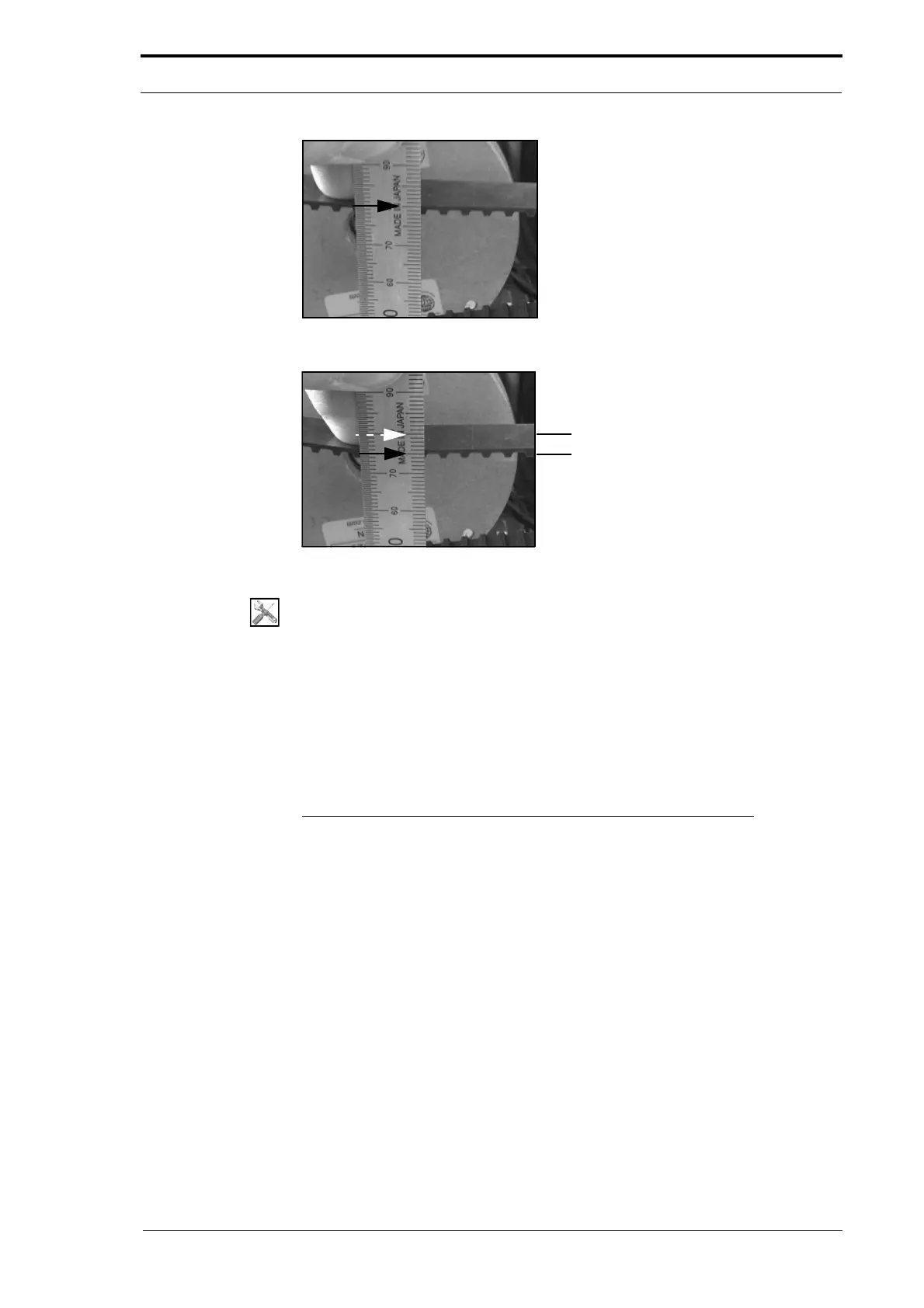
Figure 4.37 First Measurement
Figure 4.38 Second Measurement
Tools:
• 6” Steel Rule.
Before you start:
• Remove the motor cover (See Section 4.2.2).
(1) Put a 6" steel rule adjacent to the crease-motor belt (see Figure 4.37).
(2) Measure the height of the belt from the motor cover base plate.
(3) Push the belt down as far as is possible (see Figure 4.38).
(4) Measure the height of the belt from the motor cover base plate
The difference between the two height measurements should be 5.0mm.
If the tension on the crease-motor belt is not correct, it must be adjusted (see Section
4.5.12.2).
4.5.12.2 Adjust the Crease-Motor Belt Tension
The top LH screw that attaches the crease-motor
to the RH side plate is installed
through a clearance hole (a circular hole that has a slightly larger diameter than the
diameter of the screw). This screw is known as the pivot screw.
Each of the three remaining screws that attach the crease-motor to th
e RH side plate is
installed through a radial slot (a curved slot that moves around the radius of a fixed
point). This means that the crease-motor can be turned around the pivot screw to
increase or decrease the amount of tension that is applied to the motor belt.