Video Controller
19-16 MPC823e REFERENCE MANUAL MOTOROLA
VIDEO CONTROLLER
19
19.4 VIDEO CONTROLLER RAM ARRAY
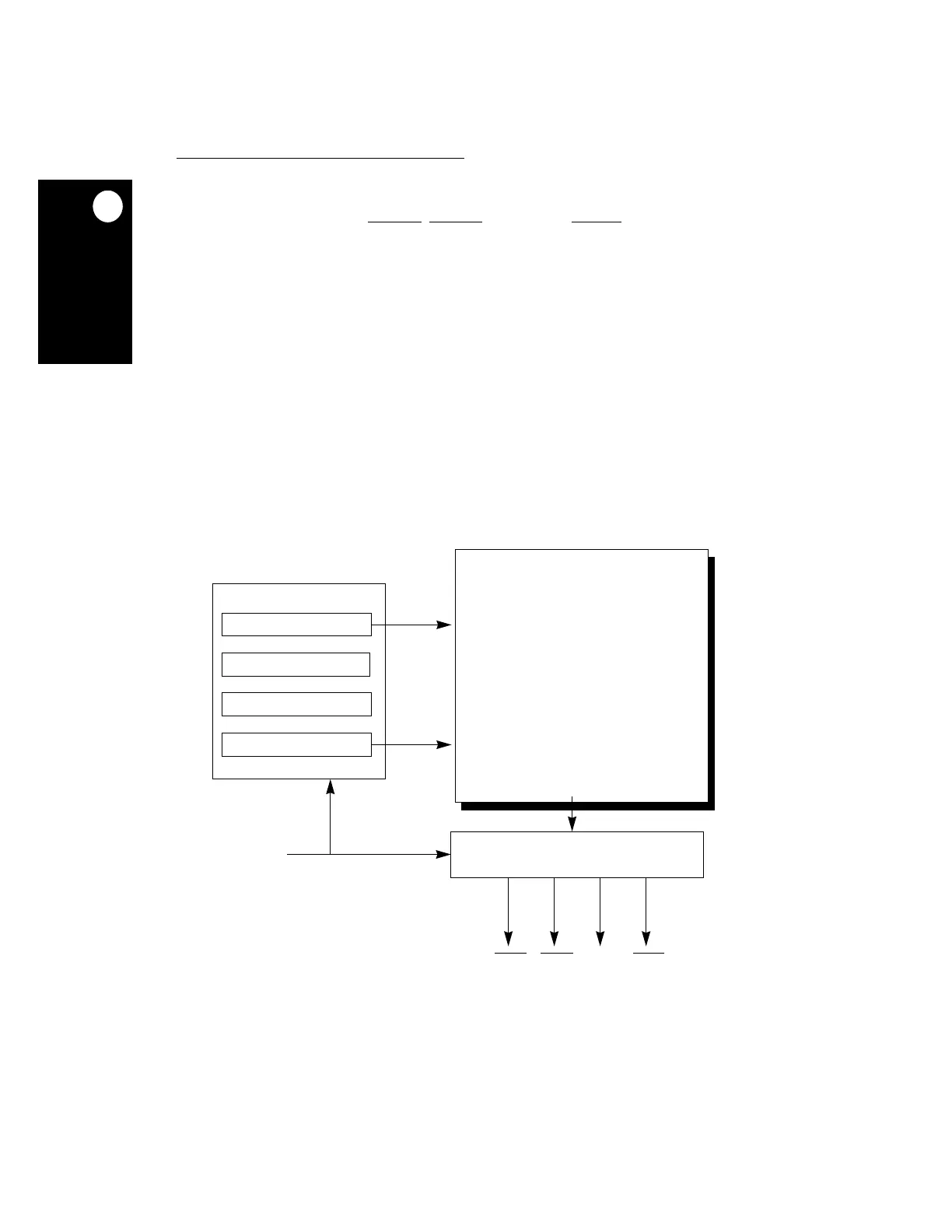
The video controller state machine controls data that is shifted out to the video port as well
as the timing patterns of the HSYNC
, VSYNC, FIELD, and BLANK signals. The video RAM
consists of two RAM arrays—RAM_0 and RAM_1—that contain 64 32-bit entries. At any
given time, one RAM array actively drives the panel and controls video controller operation,
while the other is inactive but modifiable. You can switch between the two RAMs at any time,
but your change will not take effect until the end of the frame. The CAS bit in the VSR reflects
the RAM that is active. An entry in the active RAM is read each video clock and specifies
the state of the video port signals for the next CNT video clocks. CNT is specified by a
special field within the entry. The next entry is read and used after the CNT clock periods of
the previous entry. A few entries can be repeated in a loop to generate a repetitive pattern.
Read/write operations are always directed to the inactive RAM array and can be performed
anytime the active RAM controls the video controller and display operation. Since you can
only access one RAM array (the inactive one) at a time, both RAMs are mapped to the same
address space. The RAM arrays are not initialized after power-on and any access to the
RAM array is discouraged while the video controller clock inputs are not operating. The
video RAM array block diagram is illustrated in Figure 19-4.
Figure 19-4. Video RAM Array Block Diagram
32 BITS WIDE
TIMING GENERATOR
VIDEO
VSYNC
HSYNC FIELD BLANK
ADDRESS GENERATOR
RAM ARRAY 0
CLOCK
CURRENT ENTRY POINTER
ENTRY DURATION COUNTER
LOOP COUNTER
LOOP START POINTER
64
ENTRIES
DEEP
 Loading...

