Memory Controller
MOTOROLA MPC823e REFERENCE MANUAL 15-31
MEMORY CONTROLLER
15
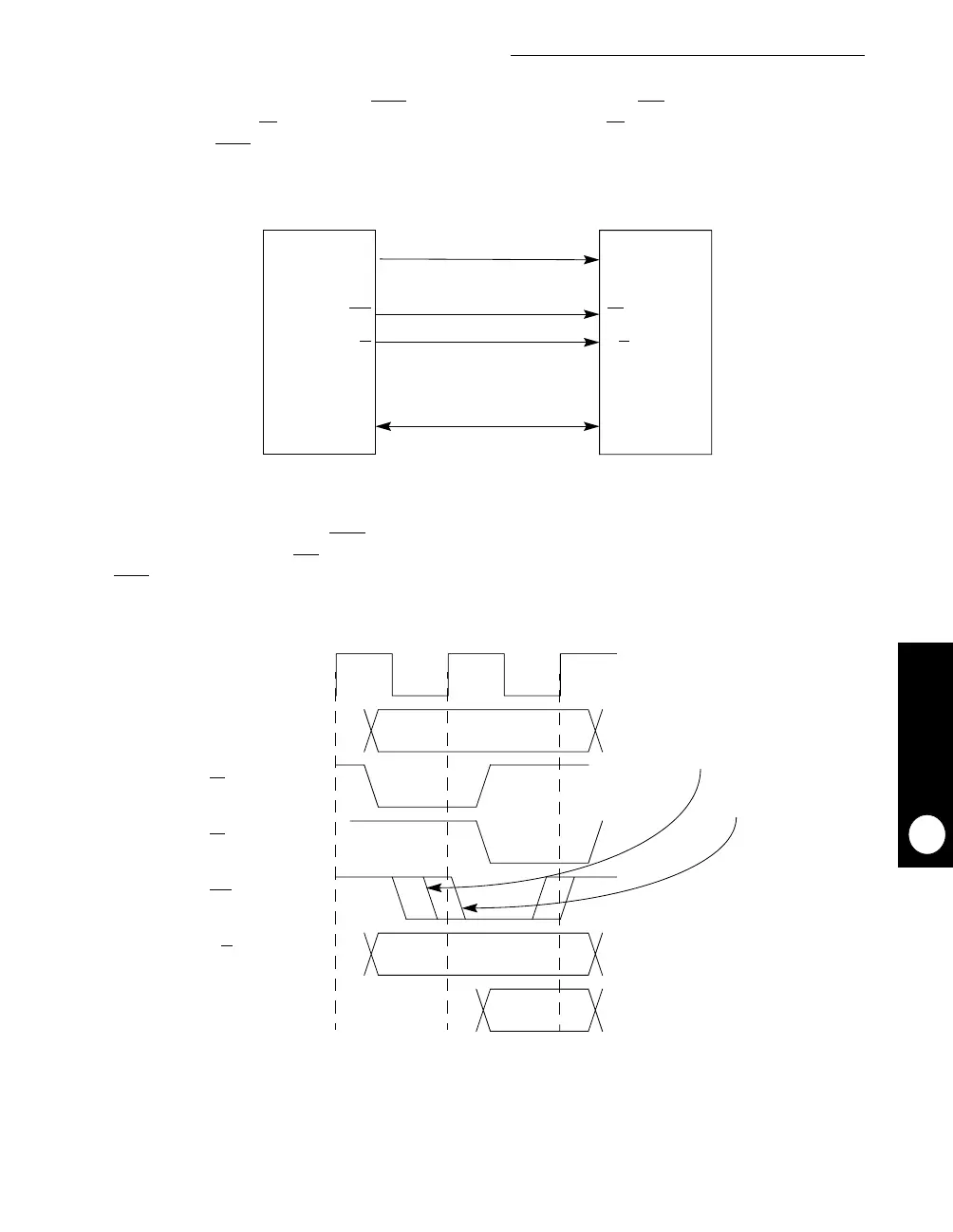
Figure 15-7 illustrates the basic connection between the MPC823e and an external
peripheral device. In this case, CSx
is connected directly to the CE signal of the memory
device and the R/W
signal is connected to the respective R/W signal in the peripheral
device. The CSx
signal is the strobe output for the memory access.
Figure 15-8 illustrates the CSx
signal as defined by the setup time required between the
address lines and the CE
signal. The MPC823e memory controller allows you to specify the
CSx
signal to meet this requirement using the ACS field of the option register.
MEMORY PERIPHERAL
Figure 15-7. GPCM Peripheral Device Interface
Figure 15-8. GPCM Peripheral Device Basic Timing (ACS = 10 or 11 and TRLX = 0)
ADDRESS
CE
R/W
DATA
ADDRESS
CS
x
R/W
DATA
CLOCK
ADDRESS
TS
TA
CSx
R/W
DATA
ACS = 10
ACS = 11
 Loading...

