Communication Processor Module
MOTOROLA MPC823e REFERENCE MANUAL 16-253
COMMUNICATION
16
SCCs
RXF—RX Frame
This bit indicates when a complete frame is received on the HDLC channel. This bit is set
no sooner than two clocks after the last bit of the closing flag is received.
BSY—Busy Condition
This bit indicates when a frame has been received and discarded due to a lack of buffers.
TXB—Transmit Buffer
This bit indicates that a buffer has been transmitted on the HDLC channel. This bit is set no
sooner than when the last bit of the closing flag begins its transmission if the buffer is the
last one in the frame. Otherwise, this bit is set after the last byte of the buffer is written to the
transmit FIFO.
RXB—Receive Buffer
This bit indicates that the HDLC channel received a buffer that is not a complete frame.
16.9.16.12 SCCx HDLC MASK REGISTER.When a serial communication controller is in
HDLC mode, the 16-bit, read/write SCCx mask register is referred to as the SCCx HDLC
mask register (SCCM–HDLC). It has the same bit formats as the SCCE–HDLC register. If a
bit in this register is a 1, the corresponding interrupt in the SCCE–HDLC register is enabled.
If the bit is zero, the corresponding interrupt in the SCCE–HDLC is masked.
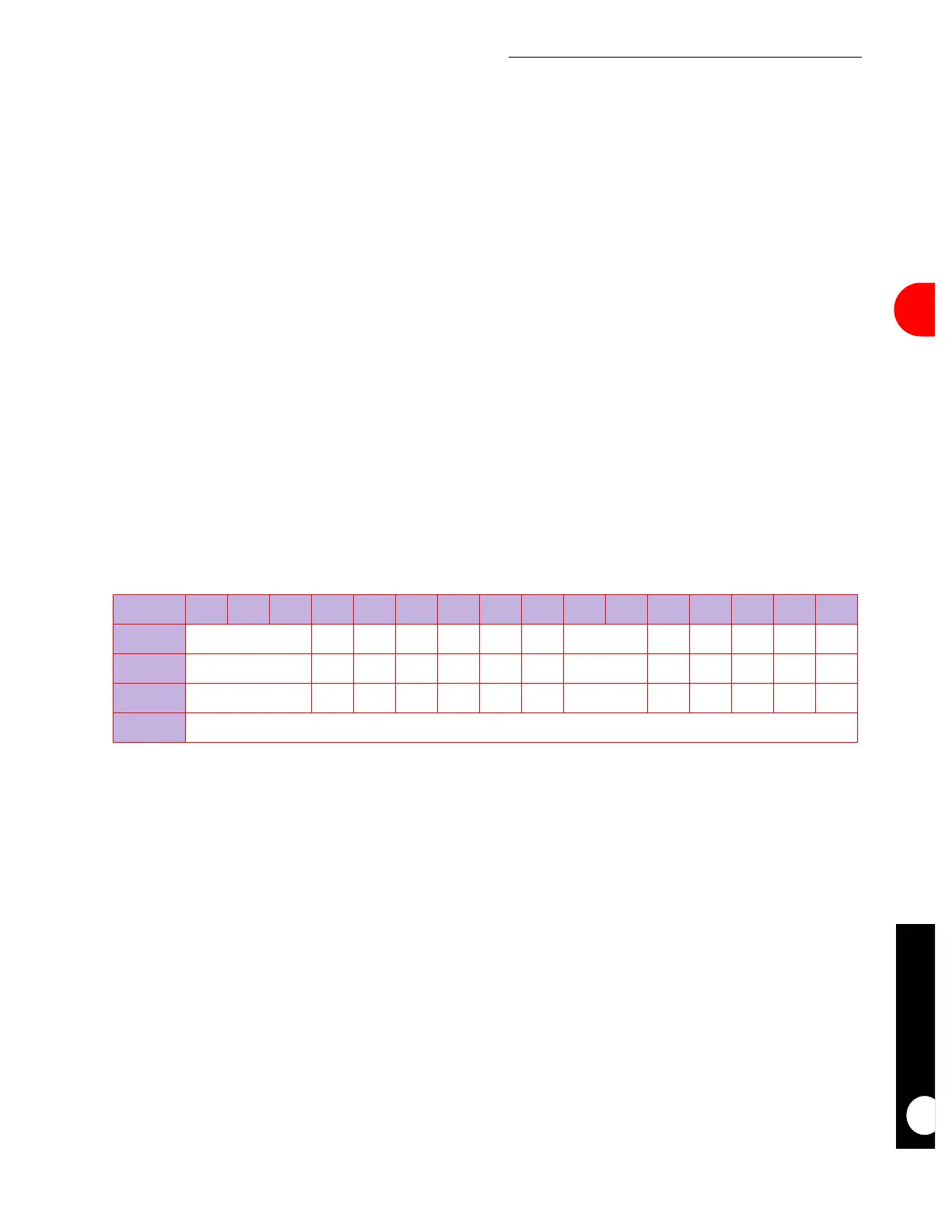
SCCM–HDLC
BIT 0 1 2 3 4 5 6 7 8 9 10 11 12 13 14 15
FIELD RESERVED GLR GLT DCC FLG IDL GRA RESERVED TXE RXF BSY TXB RXB
RESET 0 000000 0 00000
R/W R/W R/W R/W R/W R/W R/W R/W R/W R/W R/W R/W R/W R/W
ADDR (IMMR & 0xFFFF0000) + 0xA34