Communication Processor Module
16-480 MPC823e REFERENCE MANUAL MOTOROLA
PORTS
COMMUNICATION
16
PROCESSOR MODULE
16.14.3 The Port A Registers
Port A has four 16-bit, memory-mapped, read/write control registers.
16.14.3.1 PORT A OPEN-DRAIN REGISTER. The port A open-drain register (PAODR)
indicates when the port pins are configured in a normal or wired-OR configuration. Three of
the PAODR bits can be open-drain to correspond to those pins that have serial channel
output capability. The other bits are always zero. PAODR is cleared by system reset.
Bits 0–8, 10–11, 13 and 15—Reserved
These bits are reserved and must be set to 0.
OD9–OD15—Open-Drain Pins 9-15
0 = The I/O pin is actively driven as an output.
1 = The I/O pin is an open-drain driver. As an output, the pin is actively driven low.
Otherwise, it is three-stated.
16.14.3.2 PORT A DATA REGISTER. A read of the port A data (PADAT) register returns
the data at the pin, regardless of whether the pin is defined as an input or output. This allows
output conflicts to be found on the pin by comparing the written data with the data on the pin.
A write to the PADIR is latched and if the bit is configured as an output, the value latched for
that bit is driven onto its respective pin. PADAT is not initialized and is undefined at reset.
Bits 0–3—Reserved
These bits are reserved and must be set to 0.
D4–D15—Data Pins 4-15
The value written into these bits may be read on the Port A pins.
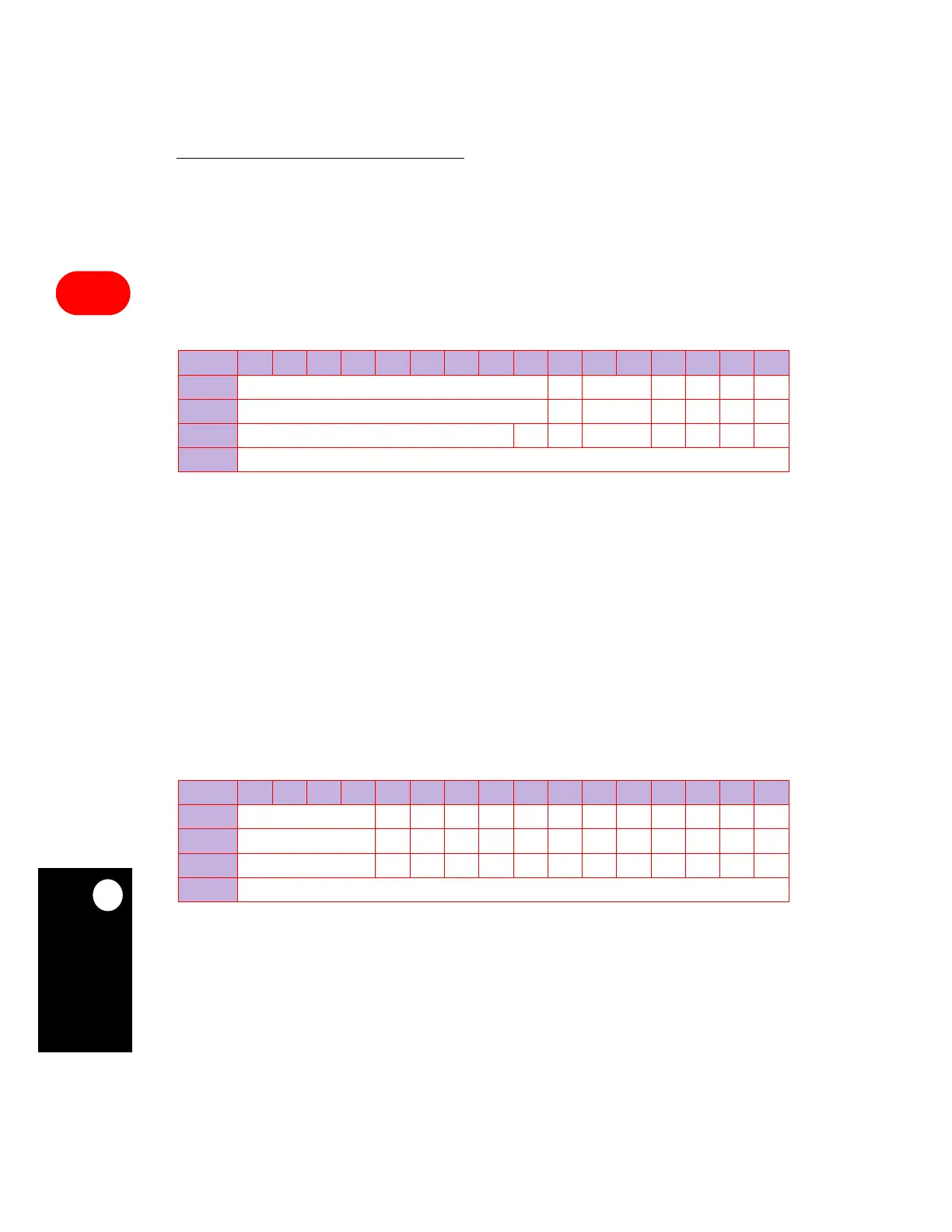
PAODR
BIT 0 1 2 3 4 5 6 7 8 9 10 11 12 13 14 15
FIELD
RESERVED OD9 RESERVED OD12 RES OD14 RES
RESET
0 0 0 0000
R/W
R/W R/W R/W R/W R/W R/W R/W
ADDR
(IMMR & 0xFFFF0000) + 0x954
PADAT
BIT 0 1 2 3 4 5 6 7 8 9 10 11 12 13 14 15
FIELD RESERVED D4 D5 D6 D7 D8 D9 D10 D11 D12 D13 D14 D15
RESET 0 000000000000
R/W R/W R/W R/W R/W R/W R/W R/W R/W R/W R/W R/W R/W R/W
ADDR (IMMR & 0xFFFF0000) + 0x956