Table 74: Associated Components
Number Description
1 Two RJ50 Ethernet Connectors. (Connectors to the Control Heads or Dual Remote Expan-
sion Head.)
CAUTION: Dual Remote Expansion Heads are only compatible with Ethernet Re-
mote Heads. Do not mix Ethernet Control Heads with non-Ethernet Control Heads.
2 RJ50 Connector (Connects to TETRA SIM card reader or RJ-45 Ethernet)
3 9-Pin subD Connector
NOTE: Use an appropriate RJ50 Ethernet cable to connect Control Heads or Dual Remote Expansion
Head. Do not use TELCO cables.
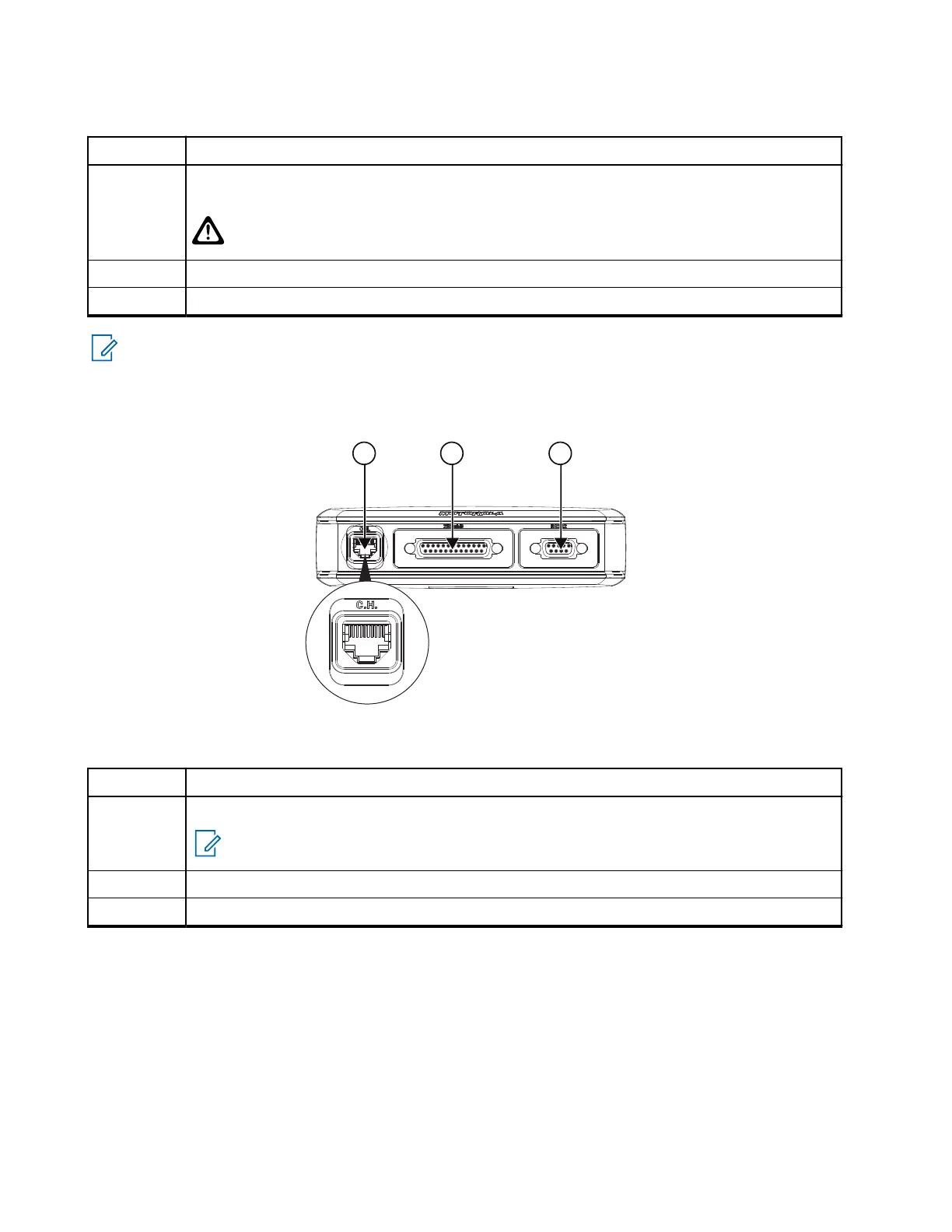
Figure 67: Databox Expansion Head – Front View and Connector Location
Table 75: Associated Components
Number Description
1 10-pin RJ50 Ethernet Connector, Front View,
NOTE: This is a connector to the Control Head and not to a microphone.
2 25-pin subD Connector
3 9-pin subD Connector
MN009998A01-AA
Chapter 4: Connectors and PIN Assignment
102
 Loading...


