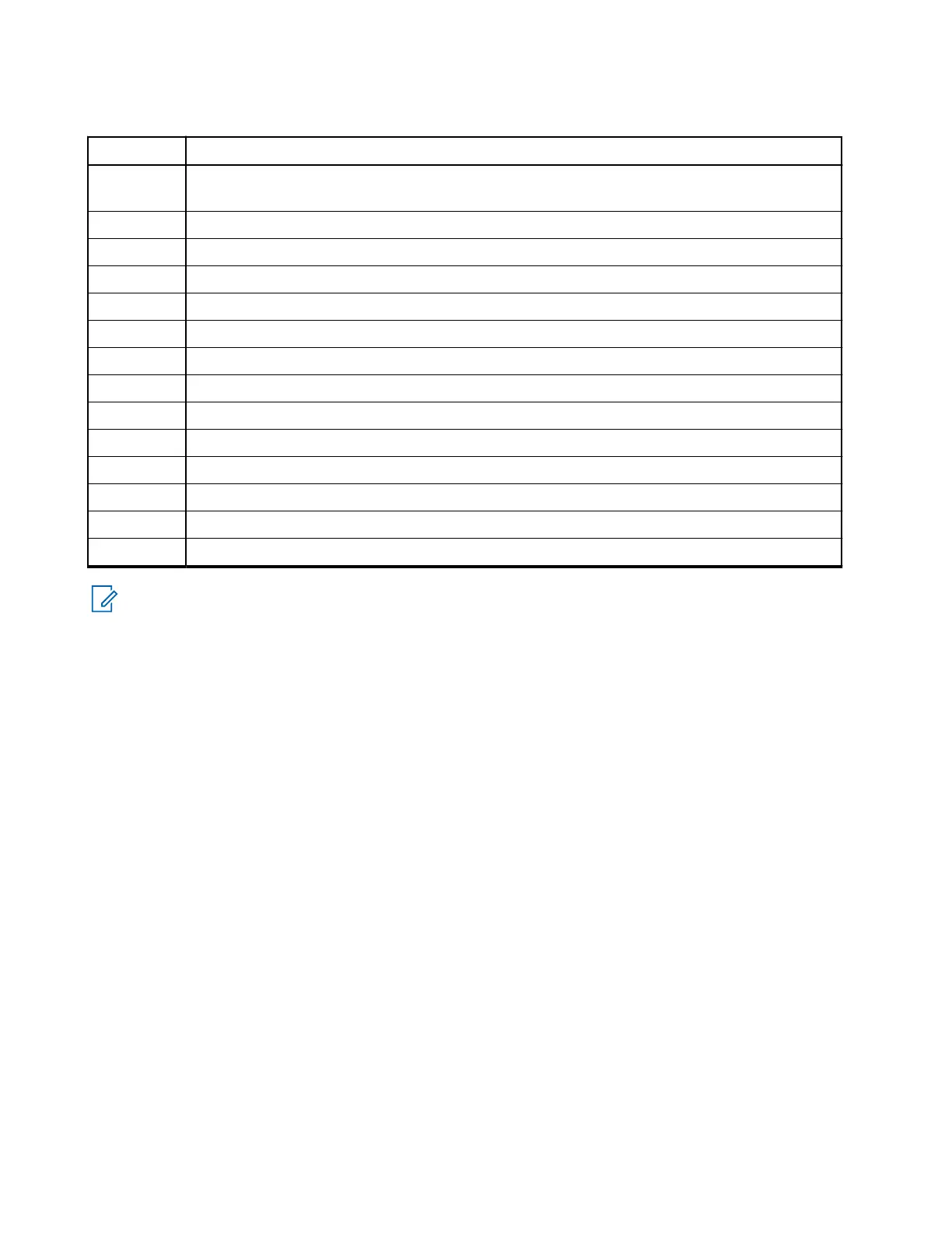
Table 55: Junction Box Installation Description
Number Description
1 Connecting cable between junction box and mobile (MXM600) terminal (Accessory plug on
rear side of the transceiver)
2 GCAI connector for Mobile Microphone Port (MMP) audio accessories
3 USB-C for programming and data (PEI)
4 Accessory plug
5 Mic +2 (smart noise canceling visor mic)
6 Mic GND
7 Mic +1
8 GND
9 1-Wire
10 Emergency cable
11 Ignition sense cable
12 External PTT
13 Speaker
14 Laptop
NOTE: The junction box PCB is not repairable. Order a new junction box as necessary.
3.6.1
Installing the Junction Box
The junction box can be installed horizontally or vertically. The junction box has no connector sealing and is
designed for use in locations that are not exposed to dust and water.
Procedure:
1. Secure the data junction box using the four screws supplied with the kit.
2. Connect the connection cable PMKN4302_ (5 m in length), PMKN4301_ (4 m in length), or
PMKN4300_ (2 m in length) from the junction box to the accessory connector on the rear side of
the transceiver.
The cable used is for installation purposes only, and must be ordered separately.
3. Fasten the cable with the plug screws.
3.6.2
Connecting Accessories to the Junction Box
Procedure:
1. Connect all accessories to the junction box.
2. Connect the cable from the mobile terminal to the junction box.
3. Connect the programming cable to the junction box, if required.
MN009998A01-AA
Chapter 3: Radio Installation
78