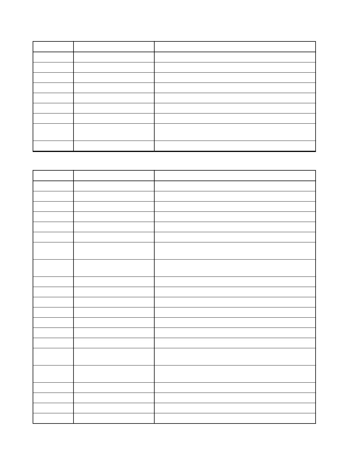
Pin Function Description
4 GND Ground
5 EXTERNAL-PTT External PTT
6 5VD + 5 V regulated
7 HANDSET_AUDIO Handset audio
8 BUS + Either SBEP or Serial Communication Interface
9 INT_MIC Microphone input – impedance of 560 Ω
10 FLT_A + Filtered A+
11 ON_OFF_CONTROL_SV Terminal On/Off Control shared with Enhanced Control
Head request
12 GND Ground
Table 68: Transceiver Pin Assignment of the Expansion Board Connector (40-Pins)
Pin Function Description
1 GND Ground
2 EXPH_GPIO1 New GPIO reserved.
3 SPIB_CLK Part of the QSPIB
4 GND Ground
5 FLT_A+ Continuous battery voltage for sense via 22 Ω
6 RESET_OUT Reset, it is an output to reset the device.
7 ON_OFF_BR On/Off functionalities. Connected to dual core processor at
1.8 V level
8 ON_OFF_CONTROL_5V Terminal On/Off Control shared with Enhanced Control
Head Request
9 3V3_DIG 3.3 V Sense Output (max 10 mA)
10 EXP_REQ Request Line from 4Wire / UART
11 SPIB_CS_UART Part of the QSPIB (chip select) for 4wire RS232 UART
12 SPIB_CS_NEW For future use; 1.8 V logic level
13 SPIB_MISO Part of the QSPIB
14 I2C_SDA I2C Data; 1.8 V logic levels
15 SPIB_MOSI Part of the QSPIB
16 IRQ-40-pin Interrupt for external device for future use; 1.8 V logic lev-
els.
17 CH_ON_OFF_OUT2 I/O for on/off functional support for multiple control-head;
1.8 V logic levels
18 GND Ground
19 INT_MIC Microphone Input - impedance of 560 Ω
20 GND Ground
21 EXPANSION_PTT Expansion PTT
MN009998A01-AA
Chapter 4: Connectors and PIN Assignment
92