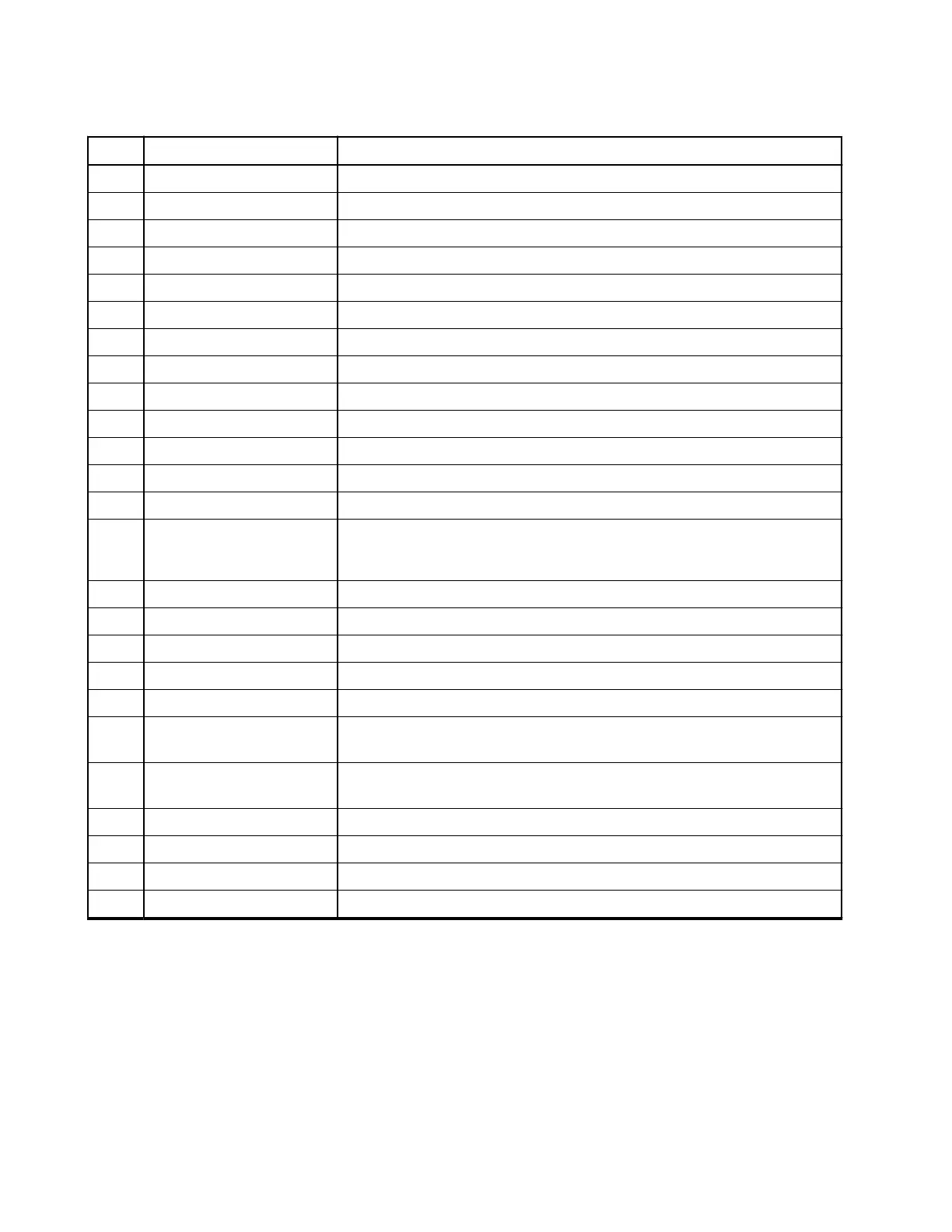
Table 77: 25-Pin SubD Connector Pins
PIN Function Description
1 GND Ground
2 RS232_SCI_TX Transceive data (RS232 line with RS232 level)
3 RS232_SCI_RX Receive data (RS232 line with RS232 level)
4 RS232_RTS Request to Send (RS232 line with RS232 level)
5 RS232_CTS Clear to Send (RS232 line with RS232 level)
6 FLT_A+ Filtered unswitched UB+/200 mA
7 Signal_GND Ground for RS232
8 Not Connected NC
9 Not Connected NC
10 Not Connected NC
11 Not Connected NC
12 SW_B+ Switched B+/100 mA
13 Not Connected NC
14 ON_OFF_CONTROL /
FLASH_MODE
● Switch into flash mode (connect Pin 14 with 6)
● On/Off control for Standard Control Head
15 Not Connected NC
16 INT_MIC Microphone analog input of 80 mV RMS, 600 Ω impedance, 9 V
17 Not Connected NC
18 Not Connected NC
19 GROUND Ground
20 IGNITION Connecting this pin to the ignition line of the vehicle will automatically
turn on your radio if the ignition of the vehicle is turned on
21 ON_OFF_GND This is the On/Off control for the old Control Head “J” (MTM300
Control Head)
22 EXPANSION_PTT Expansion PTT works together with INT_MIC
23 Not Connected NC
24 HANDSET_AUDIO Handset audio to earpiece impedance has to be > 200 Ω
25 Not Connected NC
4.5.3
9-Pin SubD Connector
Dual Remote Expansion Head (DREH):
The pin assignment of this 9-pin subD connector follows the requirements of an RS232 standard interface
with the RS232 voltage level. The cable used is a standardized serial interface cable that allows connecting
a data device with an RS232 Interface such as a PC, laptop, console, and other devices. See Connecting
Cables on page 111.
MN009998A01-AA
Chapter 4: Connectors and PIN Assignment
104
 Loading...


