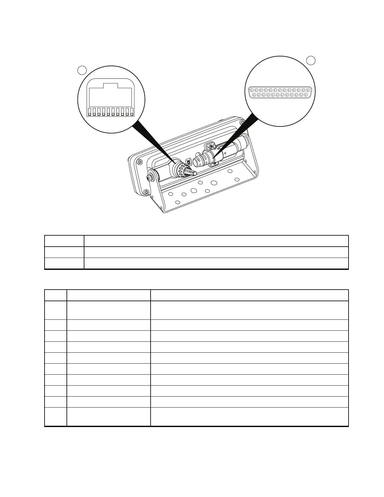
Figure 71: IP67 RECH – Rear Connectors
10
9 8 7 6 5 4 3 2 1
1 2 3 4 5 6 7 8 9 10 11 12 13
14 15 16 17 18 19 20 21 22 23 24 25
1
2
Table 84: Associated Components
Number Description
1 10-Pin Ethernet RJ50 Connector
2 25-Pin Back Connector
Table 85: 10-Pin Ethernet Connector
Pin Function Description
1 FLT_A+ (12 V) This is the voltage supply for the Control Head from power supply
or battery
2 TX+ Ethernet Ethernet transmit positive line, TX+
3 TX– Ethernet Ethernet transmit negative line, TX-
4 RX+ Ethernet Ethernet receive positive line, RX+
5 GND Main board GND
6 GND Main board GND
7 RX- Ethernet Ethernet receive negative line, RX-
8 CH_ON_OFF_OUT1_5V ON/OFF control line from Transceiver to Control Head
9 CH_ON_OFF_IN1_5V ON/OFF control line from Control Head to Transceiver
10 FLT_A+ (12 V) The voltage supply for the Control Head from power supply or
battery
MN009998A01-AA
Chapter 4: Connectors and PIN Assignment
109
 Loading...


