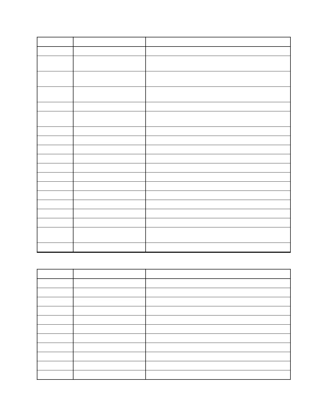
Pin Function Description
22 I2C_SCL I2C Clock; 1.8 V logic levels
23 CH_ON_OFF_OUT3 I/O for On/Off Control in multiple control heads. 1.8 V logic
level.
24 CH_ON_OFF_IN2 I/O for on/off functional support for multiple control-head;
1.8 V logic levels
25 CH_ON_OFF_IN3 I/O for on/off functional support for multiple control-head;
1.8 V logic levels
26 EXPH_ID2 Reserve pin for Expansion ID in future
27 TERMINAL ON/OFF (IGNI-
TION)
I2C Clock; 1.8 V logic levels
28 GND Ground
29 RS232_DCD Data Carrier Detect
30 RS232_TX Tx Data
31 RS232_DSR Data Set Ready
32 RS232_RTS Request to Send
33 RS232_DTR Data Terminal Ready
34 RS232_CTS Clear to Send
35 RS232_RX Rx Data
36 RS232_RI Ring Indicator
37 OPTION_DET - EXPH_ID Input pin to read the Expansion Head ID.
38 9V3 Regulated 9V3 (max 10 mA)
39 5VD Same 5 V regulator as the 12-pin connector (100 mA); for
future use.
40 HANDSET_AUDIO Handset Audio to earpiece
Table 69: Transceiver Pin Assignment of the Ethernet Connector (18-Pins)
Pin Function Description
1 GND Ground
2 GND Ground
3 GND Ground
4 GND Ground
5 Ethernet RXM RX-
6 Ethernet RXP RX+
7 FLT_A + Filtered A+
8 FLT_A + Filtered A+
9 FLT_A + Filtered A+
10 FLT_A + Filtered A+
11 FLT_A + Filtered A+
MN009998A01-AA
Chapter 4: Connectors and PIN Assignment
93