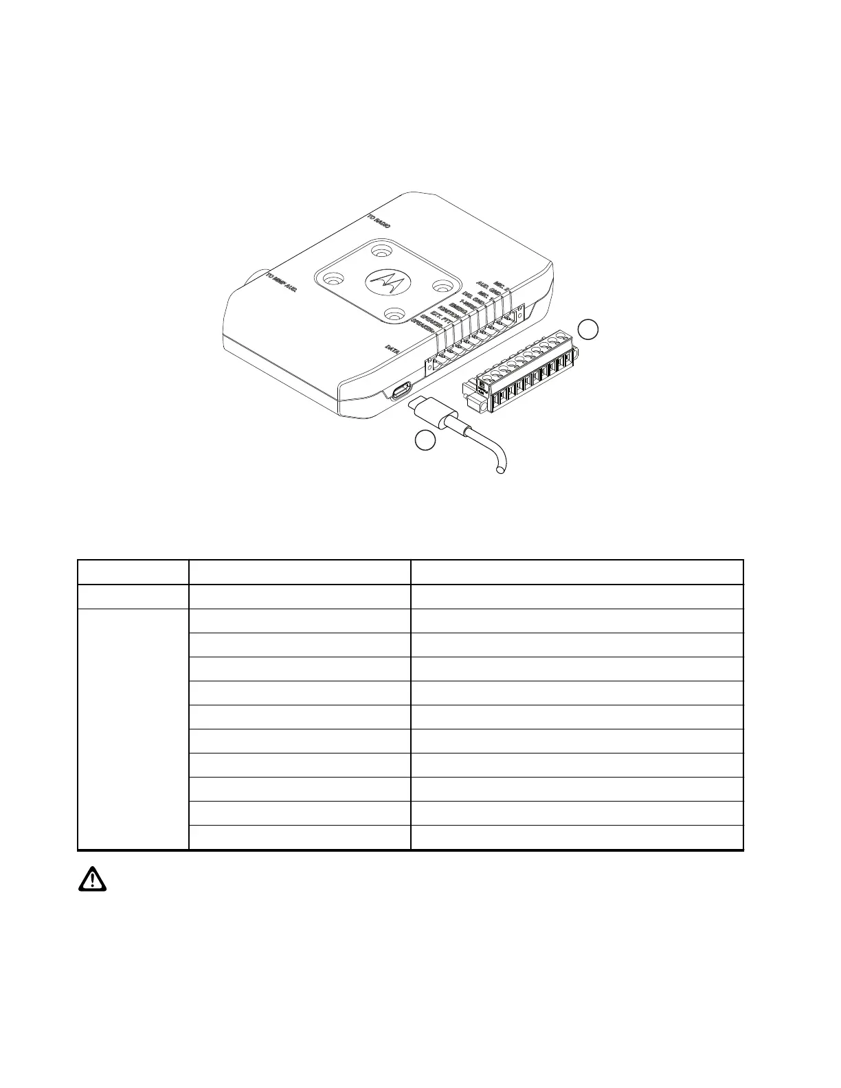
Figure 47: Connectors on the Junction Box - Front Panel
Table 57: Associated Components
No. Part/Kit Number Description
3 USB-C For programming and data (PEI)
4 pin 1 Speaker +
pin 2 Speaker -
pin 3 External PTT
pin 4 Ignition Sense
pin 5 Emergency
pin 6 1-Wire
pin 7 Digital Ground
pin 8 MIC_1
pin 9 Audio Ground
pin 10 MIC_2
CAUTION: PIN 4: To short the ignition to the ground, use an adapter between your radio and the
accessory connector. Interference can cause your radio to hang.
MN009998A01-AA
Chapter 3: Radio Installation
80