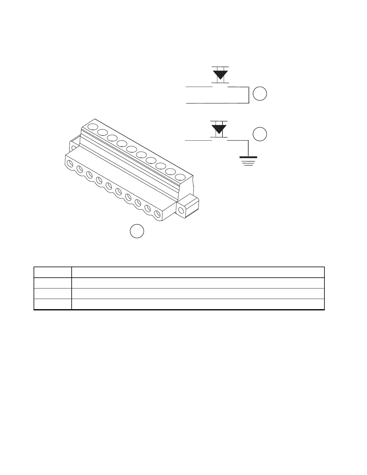
Figure 51: Connection Plan for External Push-To-Talk (PTT)
Table 61: Associated Components
Number Description
1 Junction Box 10 Pin Accessory Plug
2 External PTT Version A
3 External PTT Version B
3.6.5
Installing the Ignition Sense Cable
Procedure:
1. Connect the stripped lead of the fuse holder cable only to an ignition switched terminal of the fuse
block.
Use the supplied terminal or any other suitable terminal.
2. Mount the fuse holder using the mounting hole, and dress wires as required.
3. Cut the thin cable to the required length, crimp the supplied red lead to the stripped lead of the thin
cable, and connect it to the blue terminal of the fuse holder cable.
4. Connect the other end of the ignition sense thin cable to pin 4 of the junction box terminal.
MN009998A01-AA
Chapter 3: Radio Installation
84