Pin Function Description
12 FLT_A + Filtered A+
13 Ethernet TXM TX-
14 Ethernet TXP TX+
15 ON_OFF_BR On/Off functionality for future use. Connected to Dual Core
Processor I/O at 1.8 V level.
16 ON_OFF_CH On/Off functionality. Same as in 12-pin ON_OFF_CON-
TROL_SV.
17 GND Ground
18 GND Ground
Table 70: Transceiver Pin Assignment of the Enhanced Control Head Interface (6-Pins)
Pin Function Description
1 REEH_5V 5 V regulator (100 mA), enable SW_B+ in DEH.
2 REEH_1.8V 1.8 V Regulator for future use.
3 GND Ground
4 RE-
EH_CH_ON_OFF_OUT2_
1V8
Output pin to turn Control Head On/Off. 1.8 V logic level.
5 REEH_ID2 Reserve pin for Expansion ID in future
6 REEH_EXPH_ID Input pin to read the Expansion Head ID.
4.2
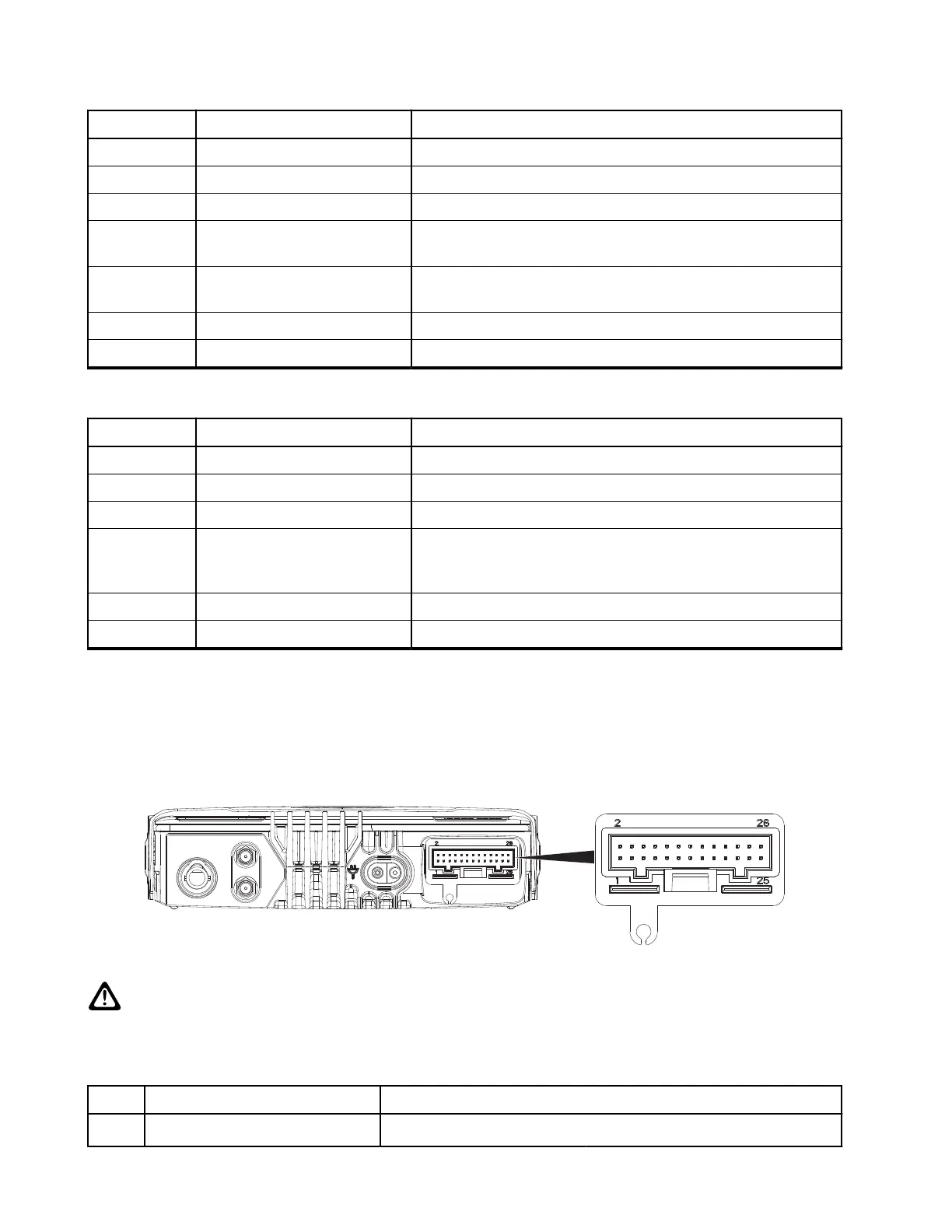
Transceiver Rear Side
Figure 58: Location of Accessory Connector – Rear Side
CAUTION: The accessory connections shown are not compatible to some other models of Motorola
Solutions radios. Check MXM600 Accessories-to-Model Chart on page 19 for the appropriate accessory
or technical manual for further information. Ensure that the accessory connector is correctly positioned.
Table 71: 26-Pin Accessory Connector
Pin Function Description
1 UART0_TXD / USBx_D+ USB1.1 – Default Host
MN009998A01-AA
Chapter 4: Connectors and PIN Assignment
94