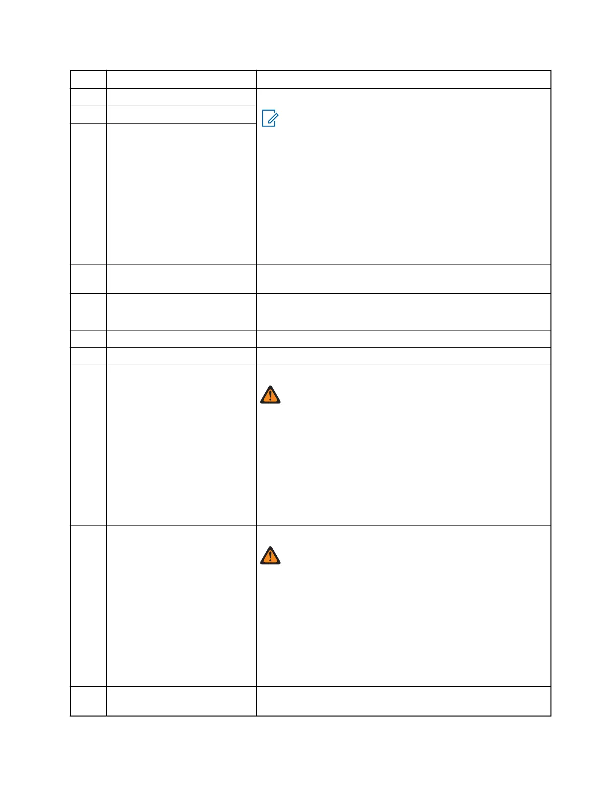
Pin Function Description
2 RS232 or UART0 – Alternative Setting
NOTE:
● The default connection is USB1.1 when the Expan-
sion Head is connected.
● UART0 is configured on the DB9 interface on the
Expansion Head if it is configured in the CPS.
● The DB9 radio monitor interface can detect cable
connection based on the pin voltage level of RX
and DTR lines.
● When the Expansion Head is not connected and
your radio is with or without BSI software, the con-
nection is configurable to UART0 in CPS codeplug.
UART0_RXD / USBx_D–
3 UART0_RTS / USBx_VBUS
4 GND_USBx
5 1-WIRE 1-Wire standard port (pulled through 2K2 to 5 V inside
U600_B), Data for RMN5054_ Microphone
6 KEYFAIL / FLASH Key load (pulled through 10 K to 5 V)
Flash input (>10 V triggers Flash mode)
7 SWB + A+ voltage (limited to 14 V) with 1 A current limitation
8 GND_MAIN Main and power ground
9 SPEAKER – Loudspeaker (PA) negative output
WARNING:
Do not ground! See Table 100: Normal Load Condi-
tions on page 134 (for MXM600) for Rated Audio Pow-
er.
Do not attach audio accessories single-ended between
the speaker out (+ or –) and ground on the rear con-
nector because the mobile radio has a Class D amplifi-
er. If it is required to connect a single-ended accessory
to the speaker out, then convert the balanced speaker
output from your radio to single-ended using a trans-
former or an electrical circuit.
10 SPEAKER + Loudspeaker (PA) positive output
WARNING:
Do not ground! See Table 100: Normal Load Condi-
tions on page 134 (for MXM600) for Rated Audio Pow-
er.
Do not attach audio accessories single-ended between
the speaker out (+ or –) and ground on the rear con-
nector because the mobile radio has a Class D amplifi-
er. If it is required to connect a single-ended accessory
to the speaker out, then convert the balanced speaker
output from your radio to single-ended using a trans-
former or an electrical circuit.
11 TX_AUDIO TX audio input (Line In, 26-pin rear connector J400, used for
audio recording)
MN009998A01-AA
Chapter 4: Connectors and PIN Assignment
95