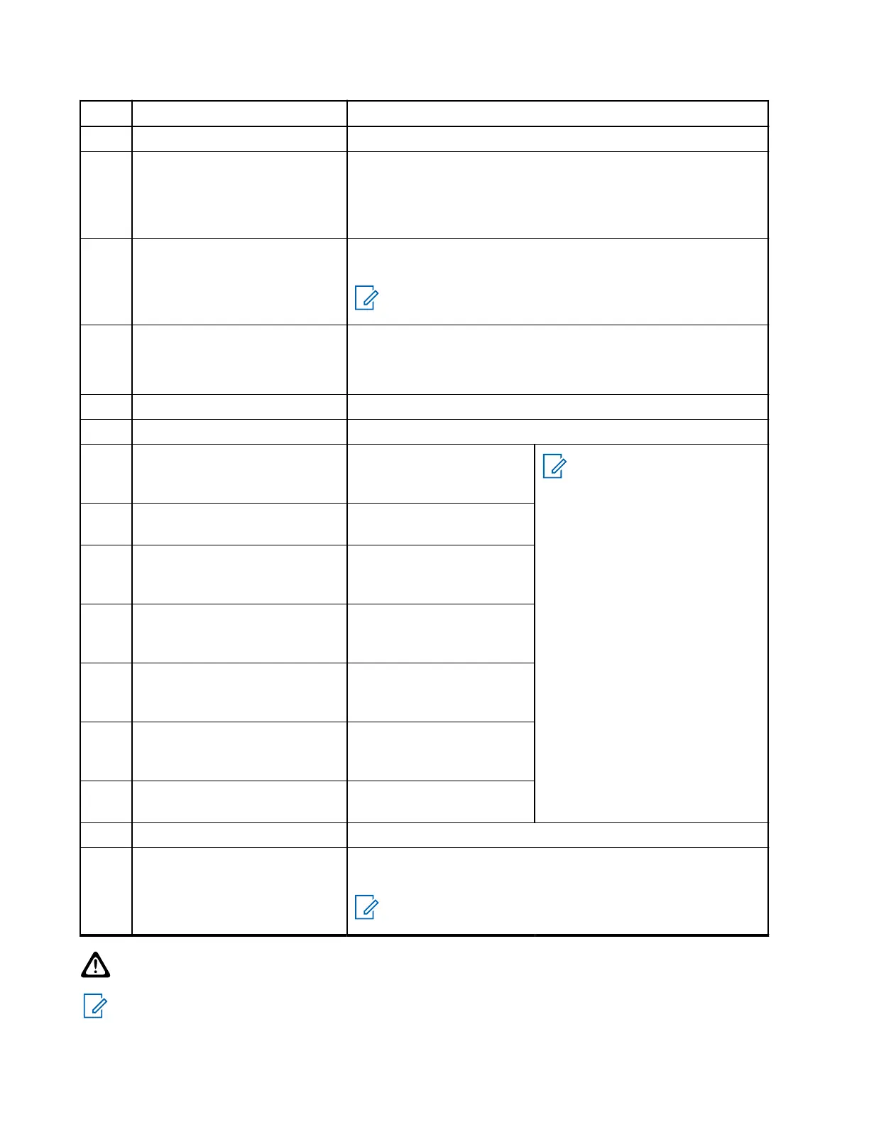
Pin Function Description
12 GND_ANA Main audio ground
13 MIC1 / EXT_MIC External microphone input (EXT_MIC) or first microphone
(MIC1) for noise canceling dual microphone input
Nominal sensitivity: 80 mV RMS, Bias voltage: 9.3 V or 2.1 V
(Selected accessory dependant)
14 RX_AUDIO RX audio output (Line Out, 26-pin rear connector J400, used
for audio playback)
NOTE: Voice recorder feature is only applicable for
software release MR15.1 and above.
15 MIC2 Microphone input (MIC2)
Nominal sensitivity: 80 mVrms, Bias voltage: 9.3 V or 2.1 V
(selected accessory dependant)
16 GND_MIC Ground (for MIC)
17 EXTERNAL_PTT PTT input (pulled through 4K7 to 5 V)
18 UART0_DTR / USBy_ID RS232 or UART1/UART0
DTR/2nd USB2.0 (OTG)
ID
NOTE:
● When Expansion
Head is connected,
the connection is
USB2.0.
● When Expansion
Head is not connect-
ed and UART0 is
configured on pins
1–4 in CPS code-
plug, the connection
is USB2.0.
● If UART0 is not con-
figured on pins 1–4
in CPS codeplug,
USB2.0/UART0 is
automatically switch-
ed depending on
which accessory is
detected.
19 HOOK_PA_EN HOOK_PA_EN input or
configurable GPIO1 (5 V)
20 UART0_TXD / USBy_TX RS232 or UART0
TXD/2nd USB2.0 (OTG)
D+
21 UART0_RTS / USBy_VBUS RS232 or UART0
RTS/2nd USB2.0 (OTG)
VBUS – 100 mA
22 UART0_RXD / USBy_RX RS232 or UART0
RXD/2nd USB2.0 (OTG)
D-
23 EMERGENCY Emergency Input (Pulled
through 24K9 to A+) –
Pull low to power on
24 UART_CTS RS232 or UART1/UART0
CTS input
25 IGNITION Ignition input (through series 15 K) – Pull > 10.8 V to power on
26 EXTERNAL ALARM External Alarm output (Pulled through 4K7 to A+) or configura-
ble GPIO2 (12 V) (open drain).
NOTE: External Alarm works only when the ignition is
off.
CAUTION: Pin 25: If the ignition line is not used, it must be grounded for example connected to pin 8.
Interference can cause your radio to hang.
NOTE: Pins 13 and 15 cannot be used or configured at the same time.
MN009998A01-AA
Chapter 4: Connectors and PIN Assignment
96