Table 91: Pin Assignment of the 10-Pin RJ50 Connector – Telephone Style Control Head
PIN Function Description
1 FLT_A+ (12 V) This is the voltage supply for the Control Head from power supply
or battery. The maximum current is 300 mA
2 ETH_TX_POS Ethernet transmit positive line, TX+
3 ETH_TX_NEG Ethernet transmit negative line, TX-
4 ETH_RX_POS Ethernet receive positive line, RX+
5 GND Main board GND
6 GND Main board GND
7 ETH_RX_NEG Ethernet receive negative line, RX-
8 CH_ON_OFF_OUT1_5V ON/OFF control line from Transceiver to Control Head
9 CH_ON_OFF_IN1_5V ON/OFF control line from Control Head to Transceiver
10 FLT_A+ (12 V) This is the voltage supply for the Control Head from power supply
or battery. The maximum current is 300 mA
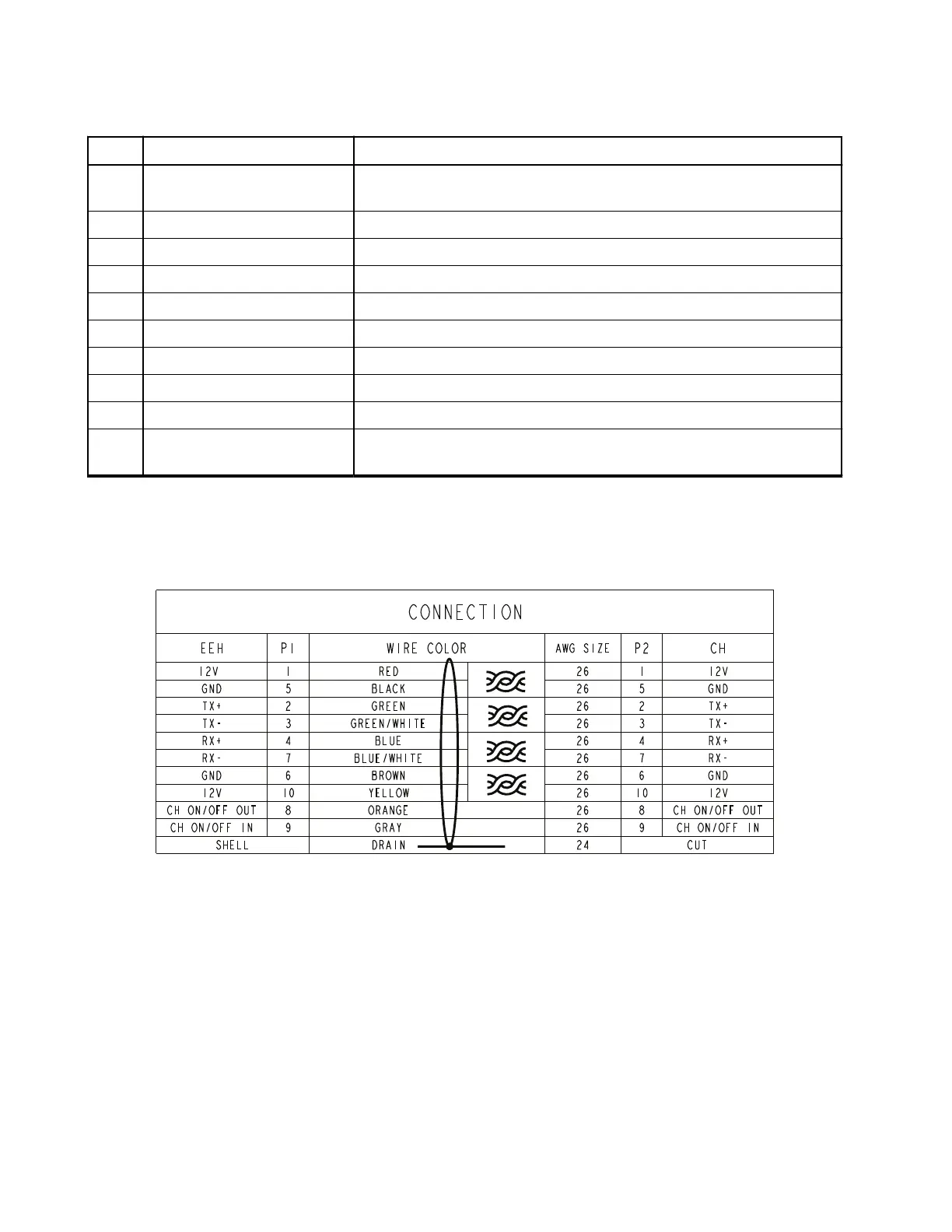
4.8.6
Ethernet Cables
Figure 78: Mobile to Control Head Ethernet Cable Pin Diagram
MN009998A01-AA
Chapter 4: Connectors and PIN Assignment
116