Chapter 4
Connectors and PIN Assignment
This section describes the connectors and pin assignments available for your radio.
4.1
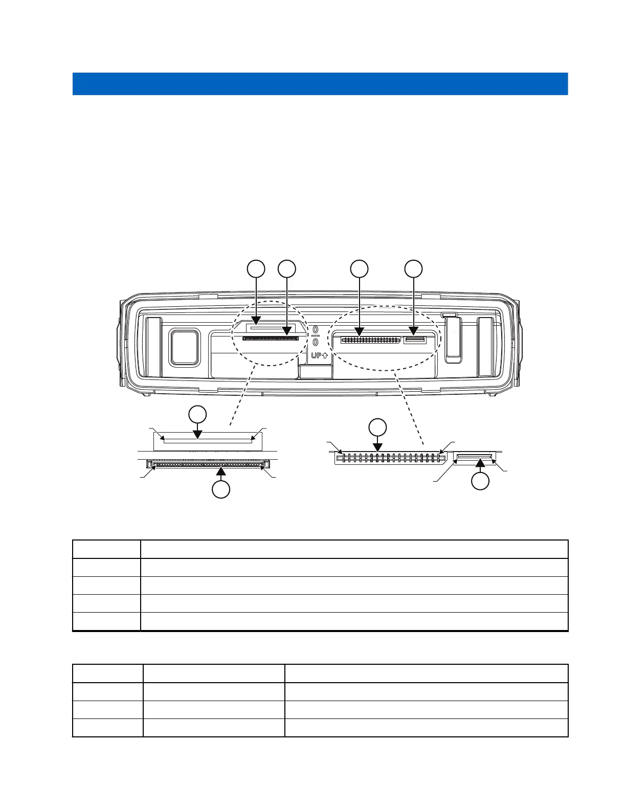
Transceiver Front – Pin Functions
Figure 57: Transceiver Front View - Dash/Desk Control Head and Expansion Head Interface
PIN 12
PIN 1
PIN 1
PIN 1 PIN 18
PIN 40
PIN 6
PIN 1
1
1
2 3 4
3
2
4
Table 66: Transceiver Front View
Number Description
1 12-Pins FPC CONN 0916162H02
2 40-Pins ZIF CONN CN002046A01
3 18-Pins FPC CONN CN002031A03
4 6-Pins FPC CONN CN002104A01
Table 67: Transceiver Pin Assignment of the Enhanced Control Head Interface (12-Pins)
Pin Function Description
1 SCI_TX Serial Communication Interface TXD
2 TBD Not-Connected – SPEAKER+ line in transceiver
3 TBD Not-Connected – SPEAKER- line in transceiver
MN009998A01-AA
Chapter 4: Connectors and PIN Assignment
91