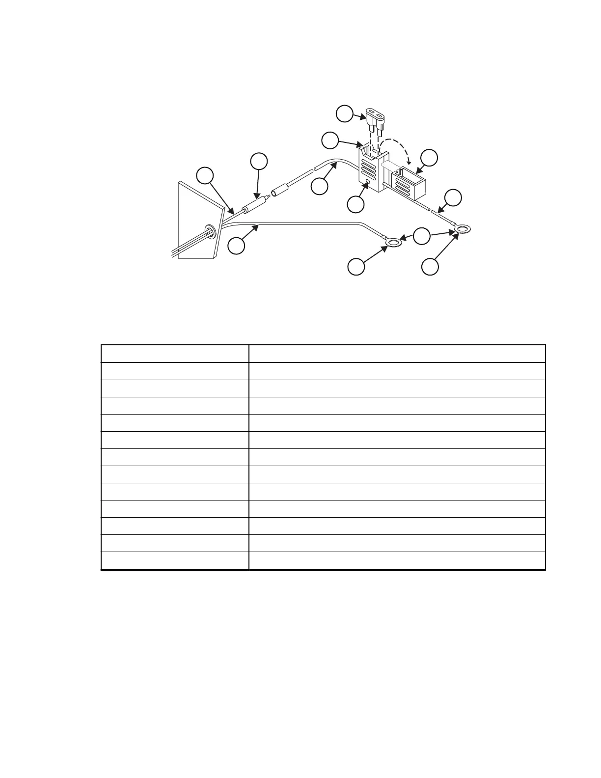
Figure 2: Power Cable Assembly
1FL08302470
1
3
5
6
4
7
2
8 11
10
12
9
Table 30: Associated Components
Number Description
1 Red lead
2 Black lead (min. 2.5 mm)
3 Adapter
4 Red lead (min. 2.5 mm)
5 Fuse holder
6 Fuse (15A)
7 Mounting hole
8 To battery (-) or chassis
9 Cover
10 Ring lugs
11 To battery (+)
12 Red lead (min. 2.5 mm)
5. Place the fuse holder close to the battery and ensure that the fuse holder is not near any hot engine
component. Mount the fuse holder using the mounting hole and dress the wires as required.
6. Insert the stripped end of the red lead of the fuse holder into the ring lug hole and crimp it. Connect
the fuse holder red adapter lead plug to the mating receptacle on the red lead of the power cable.
7. Connect the red lead ring lug from the fuse holder to the positive (+) battery terminal. Ensure that the
adapter cable is connected to the main power cable red lead.
8. Carefully check that all connections are proper. Insert the fuse into the fuse holder and close the
cover.
Postrequisites: See DC Power Cables on page 36 for power cables available for this radio.
MN009998A01-AA
Chapter 2: Vehicle Preparation
35