DCS Command System User’s Guide
Universal Locomotive & Accessory Operation
Advanced Wiring
One of the great features of the DCS system is that it is expandable and can be adapted
to each layout. The installation of the system to each layout may differ as the size and
complexity of the layout increase. Here are some general guidelines for installing DCS
on larger more complex layouts. Please see MTH's website, www.protosound2.com, for
more articles on layout wiring.
Multiple TIU Channels/Multiple TIUs
Depending on the size of your layout, you may need to use more than one TIU channel.
If your layout contains more than 300 feet of track and wiring or more than 5 engines on
the track at one time, MTH recommends using more than one TIU channel to maintain a
good DCS Track Signal (see System/Track Signal Test for more information). If you are
running engines in Command Mode only, remember the TIU Variable Channels can be
set to Fixed (see Menu/System/DCS Set Up) and all 4 channels of the TIU can be used
(AC power only). For layouts with more than 1200 feet of track and wire, MTH recom-
mends using multiple TIUs set to SUPER MODE to maintain a good DCS Track Signal.
It is important to understand the DCS remote sends a command to one TIU or multiple
TIUs at the same time and the digital command for one locomotive is sent to all tracks
connected to all TIU channels simultaneously. Therefore, the train will receive the digital
command wherever it is on the layout provided that section of the layout is connected to
a powered TIU. It is also important to remember the DCS Remote can send commands
to one TIU or multiple TIUs depending on the TIU addresses you instruct the DCS
Remote to communicate with (see Menu/System/TIU Set Up/Add TIU).
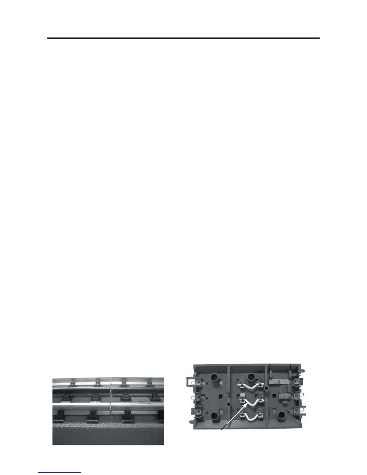
Wire Management/Track Blocks
Since DCS puts the digital signal on the center rail, digital signal strength may become an
issue as the track and wire length increase. When more than one TIU channel is used,
the track should be separated into blocks. This is easily done by insulating the rails
between blocks. In addition, the wire lengths on a terminal strip should be balanced; the
length of wire should be the same wherever possible to maximize the DCS signal on the
track. Therefore, placement of the TIU and Terminal Blocks should be centralized to
minimize the wire length going to the track.
102
Top View (40-1029)
Bottom View (40-1029)
Remove Wire to insulate center rail.