12-2 Installing a G4 Console
Remove the CT PC Box
1-, 2-, 3-Cell Color Touch Installation and Service Guide/67-2014 Rev G © 2011 Omnicell, Inc.
Supply cabinets PC box screws are accessed under the box at the front corners, using a T-10
Tor x dr iver. [8-32x3/8 SHC screws]
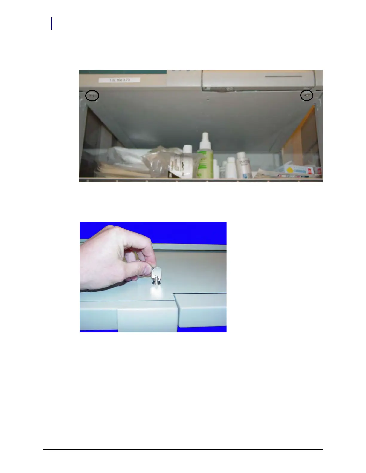
Figure 12-2. Supply cabinet
a. Slowly pull the CT PC Box from the frame until the side-mounted slides lock and stop.
b. Unlock the CT PC Box cover with the cam lock key #2036.
Figure 12-3. Unlock the CTPC Box Cover
c. Remove the cover by lifting the front end and pulling away from the cabinet.
d. Disconnect the SPC cables from the PowerCom board.