4-85
4-2 Function Mode
4
Functions
•The following shows how the power recovery restart prevention function works.
Commercial Switching
•You can use this function to drive a system with large moment of inertia during acceleration and
deceleration by using the Inverter, and during constant speed by using a commercial power supply.
•Allocate "14" (CS) to any of multi-function inputs 1 to 8 (C001 to C008).
•When the CS terminal is turned on and then off with the RUN command turned on, the Inverter starts
acceleration in synchronization with the motor rpm during free running, after the retry wait time (b003)
elapses (frequency matching start). Note that the Inverter may start at 0 Hz if:
• The motor rpm is equal to or lower than 1/2 of the base rpm
• The motor induction voltage quickly attenuates
•If frequency matching lower limit frequency setting b007 is set, the Inverter starts at 0 Hz when the
motor rpm lowers to the frequency set in b007. (Refer to page 4-38)
•Ensure that MC3 and MC2 are mechanically interlocked.
•If the earth leakage breaker (ELB) has tripped because of ground fault, the commercial power
supply circuit does not work, either. If you need backup, supply power from a commercial power
supply circuit (ELBC).
•For FWY, RVY, and CSY, use low current relays. Refer to the following sequence for timing.
•If an overcurrent trip occurs at frequency matching, extend the retry wait time (b003).
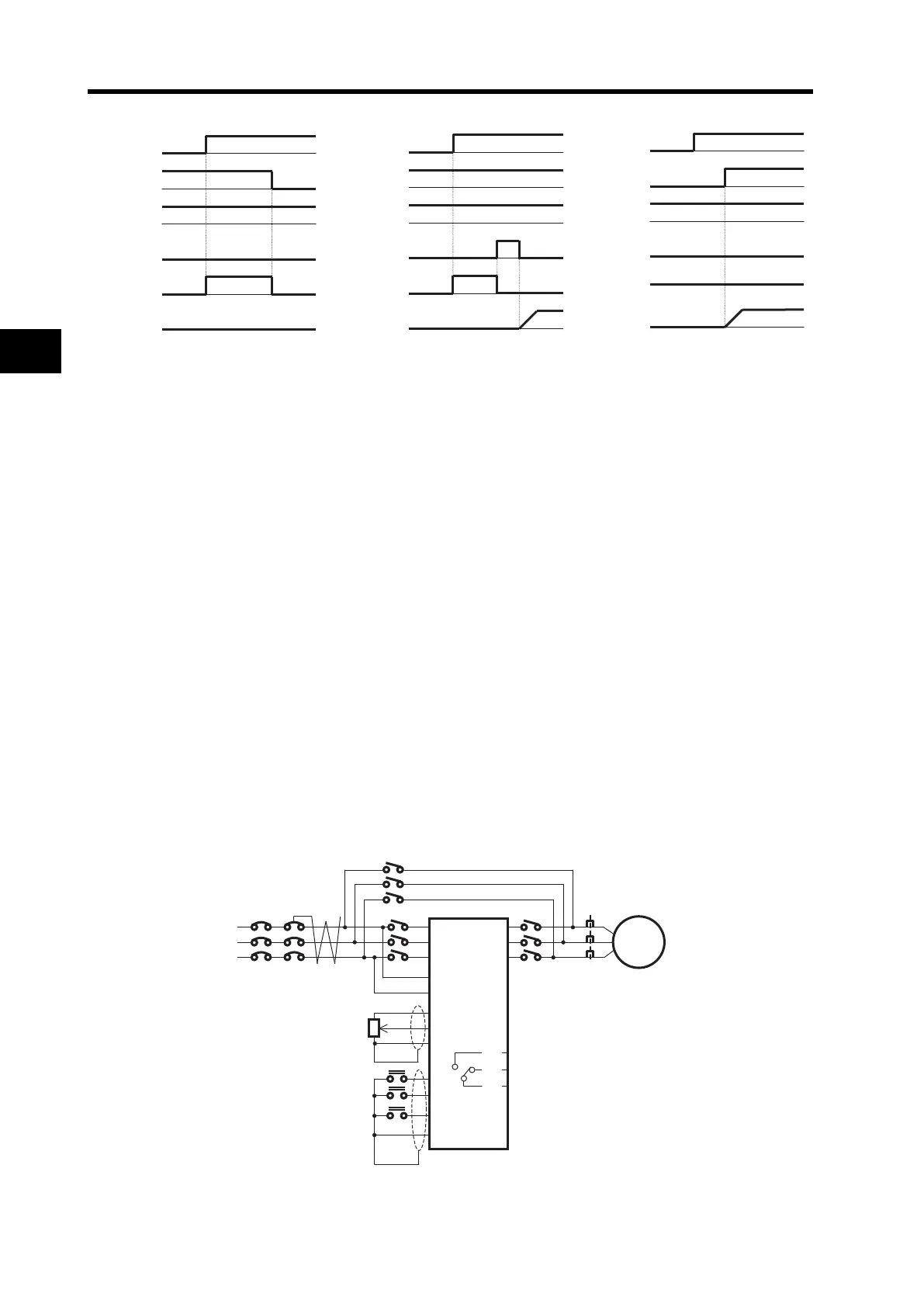
•For commercial switching operation, refer to the following examples of connections and timing of
commercial switching operation.
•At power-on, the Inverter can automatically perform retry operation. This does not require the
following CS terminal. For details, refer to "Reset" (page 4-87).
Examples of connections and timing of commercial switching operation
(Example 1)
Power
supply
FW
USP
RS
Alarm
Output
frequency
(Example 2)
Power
supply
FW
USP
RS
Alarm
Output
frequency
(Example 3)
Power
supply
FW
USP
RS
Alarm
Output
frequency
NFB
ELBC
MC2
MC1
R/L1
S/L2
T/L3
Ro
To
H
O
L
FW
RV
CS
P24
FWY
RVY
CSY
AL2
AL1
AL0
U
V
W
MC3
THRY
Motor