2-29
2-2 Wiring
2
Design
If control system recommendations conflict with these in this section: Always follow additional
recommendations of control system manufacturer. If these recommendations happen to conflict
with those in this section is usually beacuse the control system has a different internal power and
isolation structure. If the conflicting recommendation is to connect the shield to a propietary point
other than PE (power ground point) in the control connector, please respect so, and DO NOT
CONNECT THE SHIELD TO PE on the inverter side, only follow control system manufacturer
recommendations (as those are done to maximize immunity for the characteristic control system
structure).
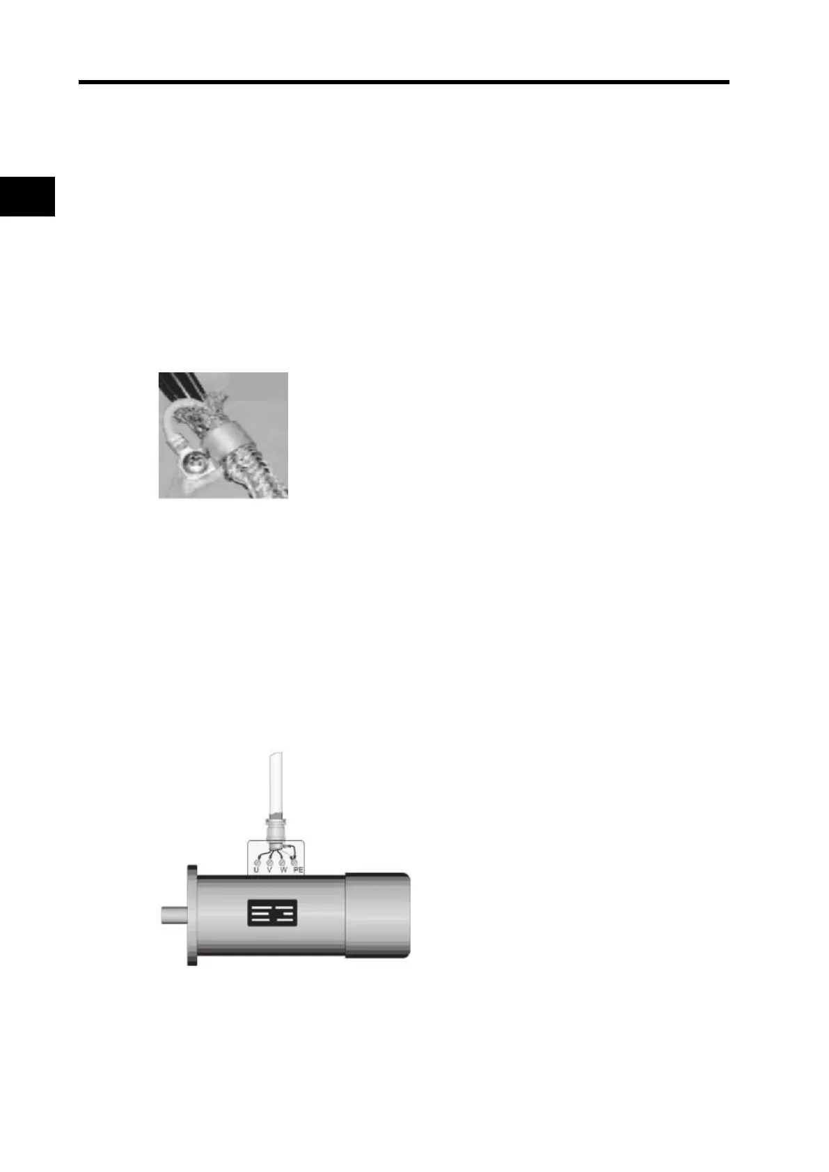
Installing the motor cable
If you use an EMC line filter or would like to observe certain limits of line-conducted interference,
the motor cable which you use must be shielded. The shield is to be grounded on both sides, over
a large area. For this purpose, turn the shield through 180º, for instance, and make large-area
contact (360º) with the metal PG screw connections.
Use only copper mesh cable (CV) with 85% coverage. Foil shields often have a higher coupling
impedance than mesh shields and are therefore unsuitable.
Some motors have terminal boxes and PG screw connections of plastic. In these cases. the shield
should be connected on the motor side to the motor housing, with as large an area as possible, by
means of a cable clamp.
Some motors have a rubber gasket between terminal box and motor housing. Very often, the
terminal boxes, and particularly the threads for the metal PG screw connections, are painted. Make
sure there is always a good metallic connection between the shielding of the motor cable, the metal
PG screw connection, the terminal box and the motor housing, and carefully remove this paint if
necessary.
The shielding should not be interrupted at any point in the cable. If the use of reactors, contactors,
terminals or safety switches in the motor output is necessary, i.e., if the shield must be interrupted,
then the unshielded section should be kept as small as possible. It is better to install the reactor,
contactor, terminal or safety switch in a metal housing with as much HF damping as possible. The
shield connection to the metal housing should again be made with the smallest possible HF
impedance, as already described.
Should no shielded motor cable be available, lay the unshielded cable in a metal tube having the
best possible shielding effect, for example. The metal tube should have good HF contact with the
frequency inverter and the motor housing, e.g., by means of appropriate clamping. Safety grounding
always takes precedence over HF grounding. If, for example, a braking chopper / rheostat is to be
connected to the DC intermediate circuit, then this connecting line, too, must be shielded. The shield
is to be connected on both sides, with a large area (e.g. to the protective ground terminal of the
rheostat). Follows EMC compliant installation for motor.