3-17
3-7 Part Names and Descriptions of the Digital Operator
3
Operation
3-7 Part Names and Descriptions of the
Digital Operator
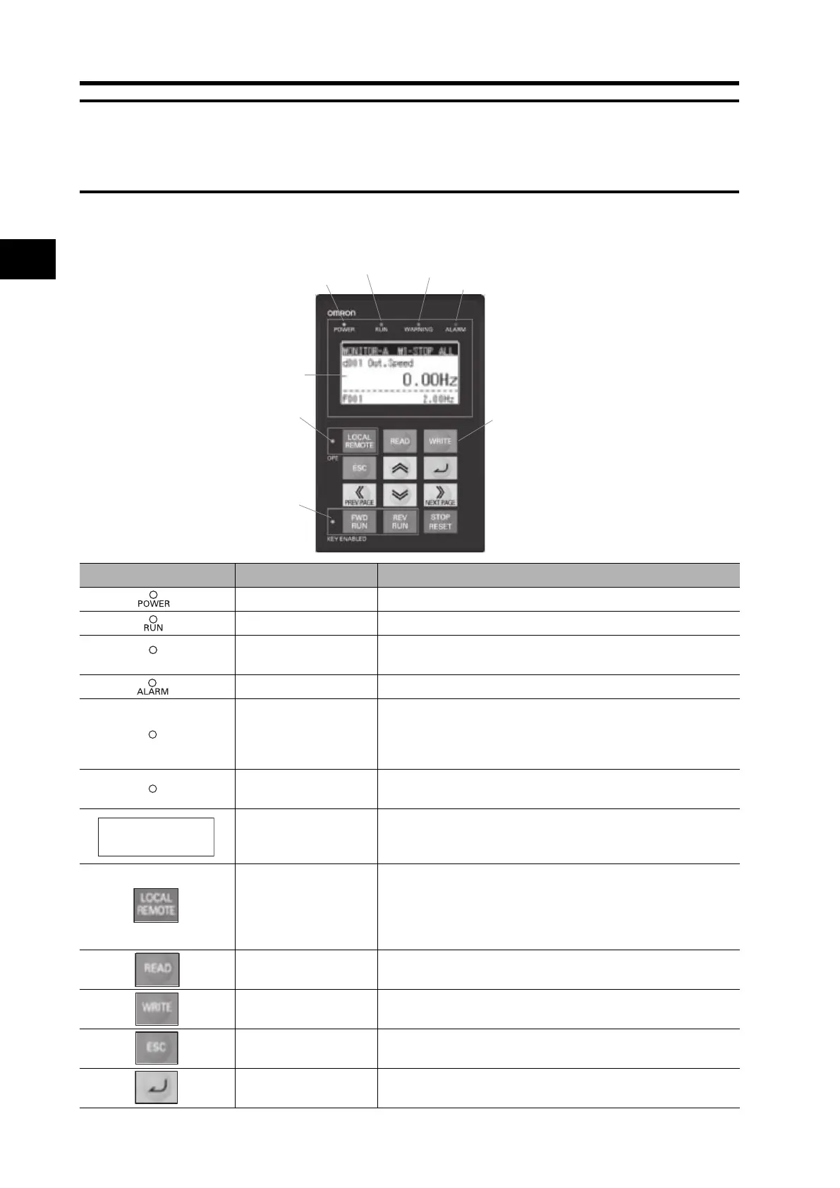
Part Names and Descriptions
RUN LED
WARNING LED
ALARM LED
LCD display
REMOTE LED
KEY
ENABLED LED
OPERATION
KEY
POWER LED
Name Function
POWER LED indicator Light on when the power is supplied to the LCD digital operator.
RUN LED indicator Light on when the Inverter is runing.
WARNING LED
indicator
Light on when set value is incorrect.
ALARM LED indicator Light on when the Inverter trips.
Remote LED
Light on when the REMOTE key makes the compulsion
operation function effective. It doesn’t light when the
compulsion operation function is effective by input terminal
OPE. (Press the key more than 2 seconds)
Key Enabled LED
Light on only when operation command is set in LCD digital
operator.
LCD Display
Displays relevant data, such as frequency reference, output
current, and set values.
LOCAL REMOTE key
It changes from Local to Remote mode. Press the key during 2
seconds to change from Local to Remote or Remote to Local.
When it is in Local the OPE led will be ON. Use Local to control
the motor with LCD digital operator keys (Run Fwd, Run Rev
and Stop/Reset).
READ key
It transfers inverter parameters to the LCD digital operator’s
memory.
WRITE key
It copies one Parameter Set or a Parameter Set + Drive
Programming saved in LCD digital operator to the inverter.
ESC key
It returns to the above layer.
SET key
It jumps to the below layer or stores the change introduces on
the edit layer (after that it jumps to the above layer).