5-62
5-26 User Parameters
Operating Functions
5
User parameters are set and checked on CX-Drive or the Parameter Unit (R88A-PR02G).
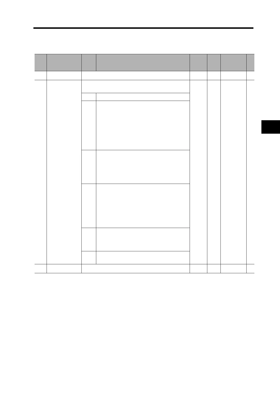
Parameter Tables
Pn
No.
Parameter name Setting Explanation
Default
setting
Unit
Setting
range
Attribute
000
Reserved
Do not change. 1 --- --- ---
001
Default Display
Selects the data to be displayed on the 7-segment LED
display on the front panel.
0 --- 0 to 4 A
0 Normal status ("--" Servo OFF, "00" Servo ON)
1
Indicates the machine angle from 0 to FF hex.
0 is the zero position of the encoder. The angle
increases when the Servomotor turns forward.
The count continues from "0" after exceeding
"FF".
When using an incremental encoder, the display
shows "nF" (not Fixed) until detecting the zero
position on the encoder after the control power is
turned ON.
2
Indicates the electrical angle from 0 to FF hex.
0 is the position where the inductive voltage on the
U phase reaches the position peak. The angle
increases when the Servomotor turns forward.
The count continues from "0" after exceeding
"FF".
3
Indicates the number (total) of MECHATROLINK-
II communications errors from 0 to FF hex.
The communications error count (total) saturates
at the maximum of FFFFh. "h" appears only for the
lowest byte. The count continues from "00" after
exceeding "FF".
Note The communications error count (total) is
cleared by turning OFF the control power.
4
Indicates the setting on the rotary switch (node
address value) loaded at startup, in decimal.
This value does not change even if the rotary
switch is turned after startup.
5 to
32767
Reserved
(Do not set.)
002
Reserved
Do not change. 0 --- --- ---

 Loading...


