4-48
4-4 Regenerative Energy Absorption
System Design
4
4-4 Regenerative Energy Absorption
The Servo Drives have internal regenerative energy absorption circuitry, which absorbs the
regenerative energy produced during Servomotor deceleration and prevents the DC voltage from
increasing. An overvoltage error occurs, however, if the amount of regenerative energy from the
Servomotor is too large. If this occurs, measures must be taken to reduce the regenerative energy
by changing operating patterns, or to increase the regenerative energy absorption capacity by
connecting an External Regeneration Resistor.
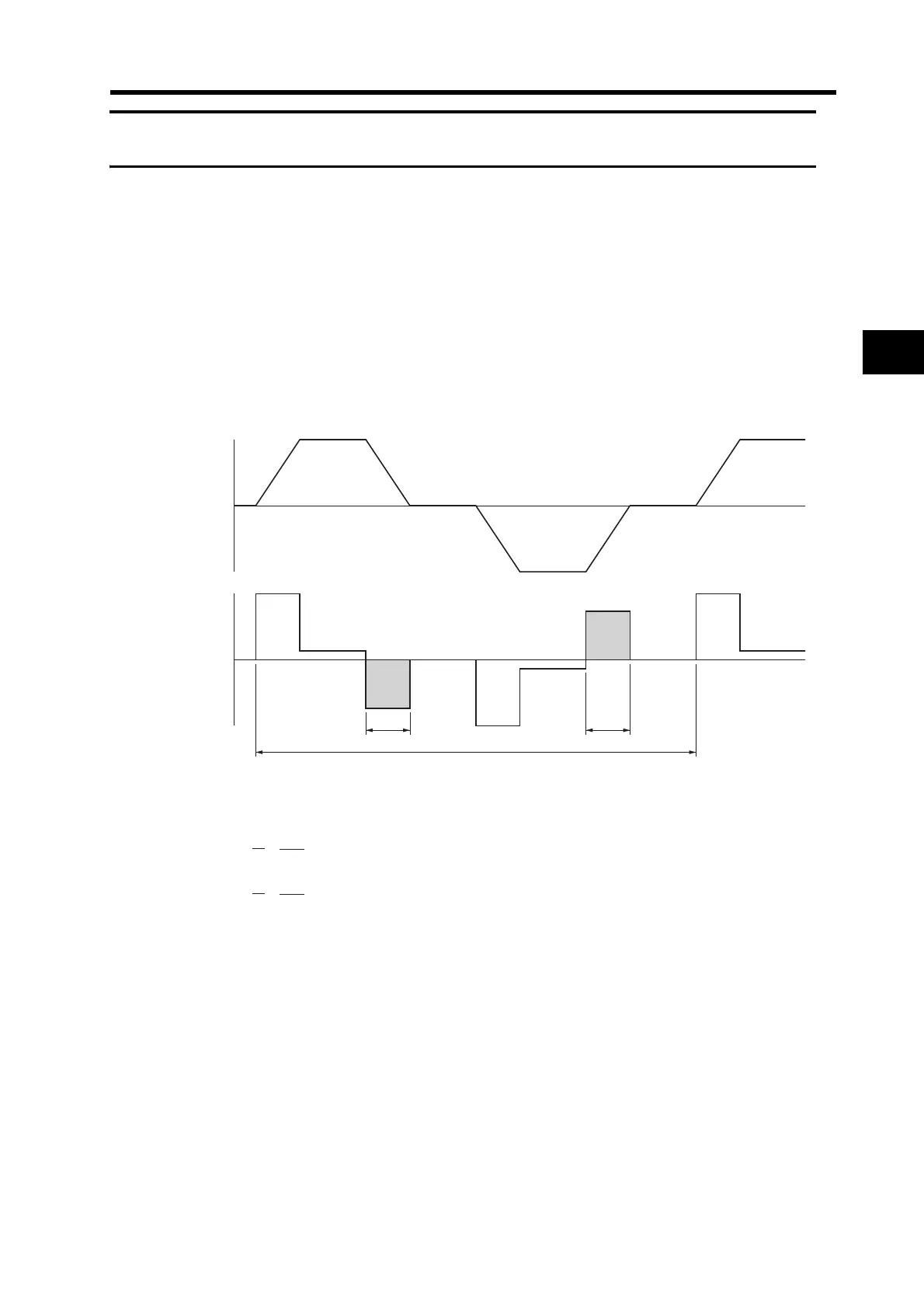
Calculating the Regenerative Energy
Horizontal Axis
In the output torque graph, acceleration in the positive direction is shown as positive, and
acceleration in the negative direction is shown as negative.
The regenerative energy values for each region can be derived from the following equations.
Note Due to the loss of winding resistance and PWM, the actual regenerative energy will be
approximately 90% of the values derived from these equations.
+N1
−N2
TD1
TD2
t 1 t 2
T
E
g1g1Eg1
Eg2g2Eg2
Servomotor
operation
Servomotor
output torque
11
1
2π
2
1
t
1TNE
D
g
=
60
****
[J]
22
2
2π
2
1
t
2TNE
D
g
=
60
****
[J]
N1, N2: Rotation speed at beginning of deceleration [r/min]
T
D1, TD2: Deceleration torque [N·m]
t
1, t2: Deceleration time [s]

 Loading...


