4-22
4-2 Wiring
System Design
4
Main Circuit and Servomotor Connector Specifications
When wiring the main circuit, use proper wire sizes, grounding systems, and anti-noise measures.
R88D-GNA5L-ML2/-GN01L-ML2/-GN02L-ML2/-GN04L-ML2
R88D-GN01H-ML2/-GN02H-ML2/-GN04H-ML2/-GN08H-ML2/-GN10H-ML2/
-GN15H-ML2
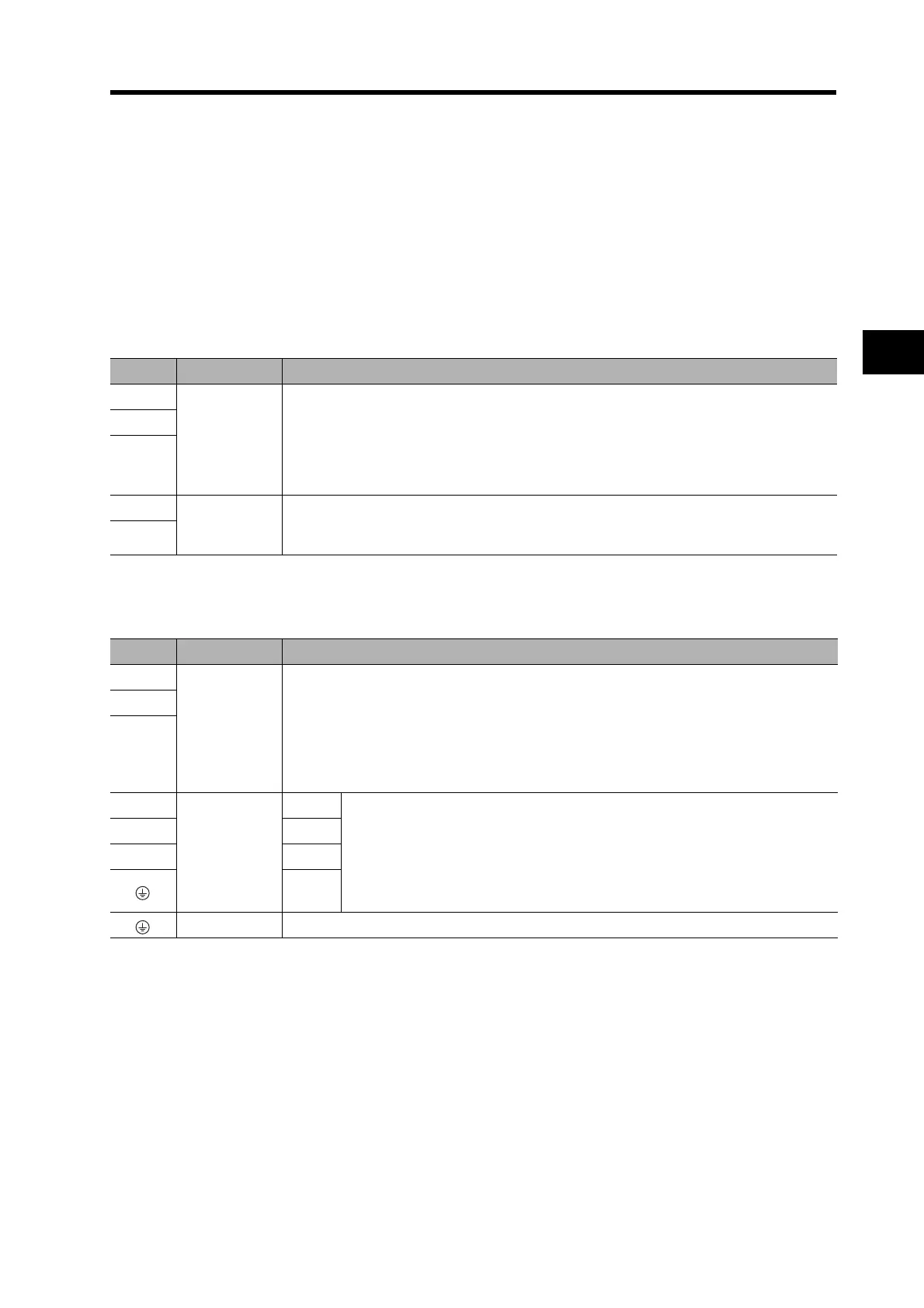
Main Circuit Connector Specifications (CNA)
Servomotor Connector Specifications (CNB)
Symbol Name Function
L1
Main circuit
power supply
input
R88D-GNL-ML2 (50 to 400 W): Single-phase 100 to 115 VAC (85 to 127 V),
50/60 Hz
R88D-GNH-ML2 (50 W to 1.5 kW): Single-phase 200 to 240 VAC (170 to 264 V),
50/60 Hz
(750 W to 1.5 kW): Three-phase 200 to 240 VAC (170 to 264 V),
50/60 Hz
L2
L3
L1C Control circuit
power supply
input
R88D-GNL-ML2: Single-phase 100 to 115 VAC (85 to 127 V), 50/60 Hz
R88D-GNH-ML2: Single-phase 200 to 240 VAC (170 to 264 V), 50/60 Hz
L2C
Symbol Name Function
B1
External
Regeneration
Resistor
connection
terminals
R88D-GNA5L-ML2/-GN01L-ML2/-GN02L-ML2/-GN01H-ML2/-GN02H-ML2/-GN04H-ML2:
Normally, do not short B1 and B2. Doing so may cause malfunctions. If there is high
regenerative energy, connect an External Regeneration Resistor between B1 and B2.
R88D-GN04L-ML2/-GN08H-ML2/-GN10H-ML2/-GN15H-ML2:
Normally B2 and B3 are shorted. Do not short B1 and B2. Doing so may cause
malfunctions. If there is high regenerative energy, remove the short-circuit bar be-
tween B2 and B3 and connect an External Regeneration Resistor between B1 and B2.
B2
B3
U
Servomotor
connection
terminals
Red
These are the output terminals to the Servomotor.
Be sure to wire them correctly.
VWhite
WBlue
Green/
Yellow
Frame ground This is the ground terminal. Ground to 100 or less.

 Loading...


