4-23
4-2 Wiring
System Design
4
R88D-GN20H-ML2/-GN30H-ML2/-GN50H-ML2
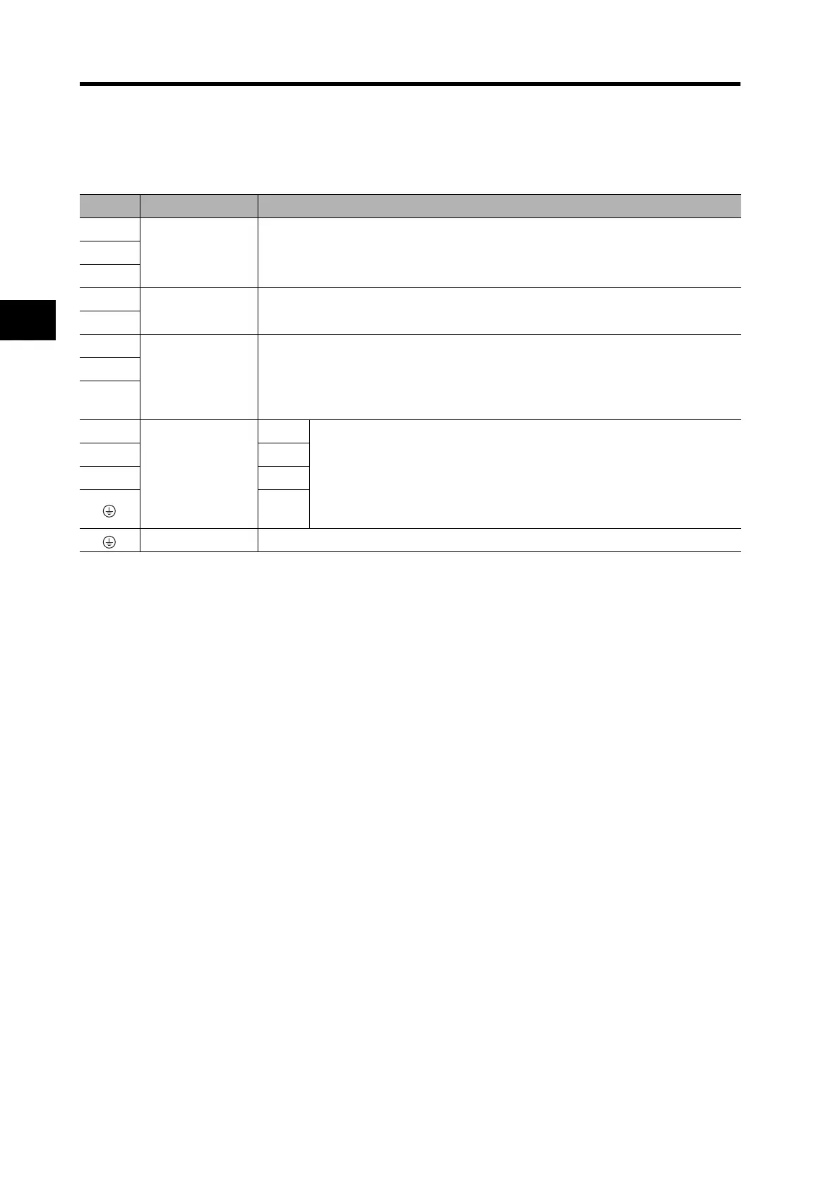
Main Circuit Terminal Block Specifications
Symbol Name Function
L1
Main circuit power
supply input
R88D-GNH-ML2 (2 to 5 kW): Three-phase 200 to 230 VAC (170 to 253 V), 50/60 HzL2
L3
L1C
Control circuit
power supply input
R88D-GNH-ML2 : Single-phase 200 to 230 VAC (170 to 253 V), 50/60 Hz
L2C
B1 External
Regeneration
Resistor
connection
terminals
2 to 5 kW: Normally B2 and B3 are shorted. Do not short B1 and B2. Doing so may
cause malfunctions. If there is high regenerative energy, remove the
short-circuit bar between B2 and B3 and connect an External Regenera-
tion Resistor between B1 and B2.
B2
B3
U
Servomotor
connection
terminals
Red
These are the output terminals to the Servomotor.
Be sure to wire them correctly.
VWhite
WBlue
Green/
Yellow
Frame ground This is the ground terminal. Ground to 100 or less.

 Loading...


