6-5
6-2 Preparing for Operation
Operation
6
Checking the Displays
7-segment LED
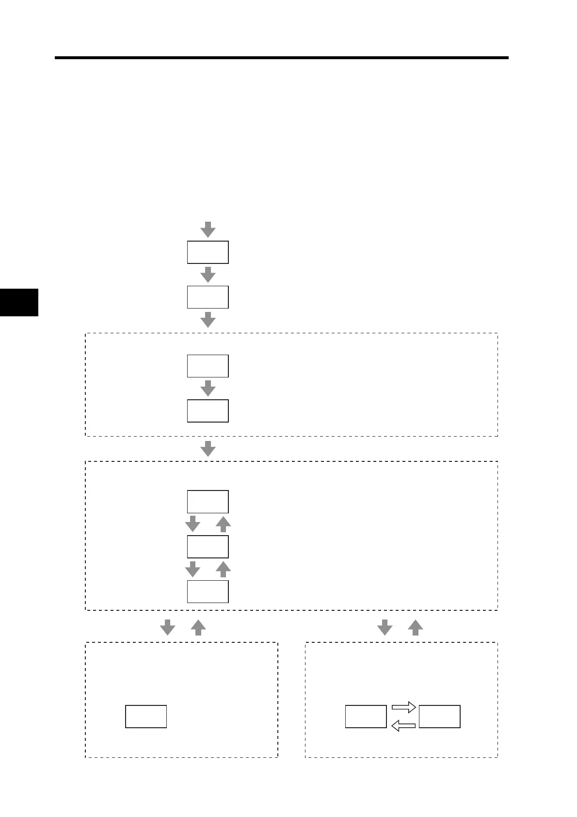
The display of the 7-segment LED on the front panel is shown below.
When the power is turned ON, the node address set with the rotary switch is displayed, followed by
the display content set by the Default Display (Pn001) parameter.
When an alarm occurs, the alarm code will be displayed. When a warning occurs, the warning code
will be displayed.
8.8.
nkak
k3k
1k6k 9k0. 0k0.
-k-k
-k-.
0k0.
Turn ON Control Power Supply
All OFF
All ON
(approx. 0.6 s)
<Node Address Display>
[nA] (Node Address)
(approx. 0.6 s)
Rotary switch setting (for MSD = 0, LSD = 3)
(Time set by the Power ON Address Display
Duration Setting (Pn006))
<Normal Display (when the Default Display (Pn001) is set to 0)>
Main Power Supply ON
and Network Established
Servo ON
Alarm Issued
<Alarm Display>
War
ning code (2 s) Normal Display
(approx. 4 s)
Alarm code flashes in decimal display
(Below is an example for overload)
Alternates between warning code (hex)
and normal display
(Below is an example for overload)
<Warning Display>
Warning Issued
Warning Cleared
Alarm Cleared
Servo OFF
[- -] + right dot ON
[00] + right dot ON
Main Power Supply OFF
or Network Not Established
[- -]

 Loading...


