3-15
3-1 Servo Drive Specifications
3
Specifications
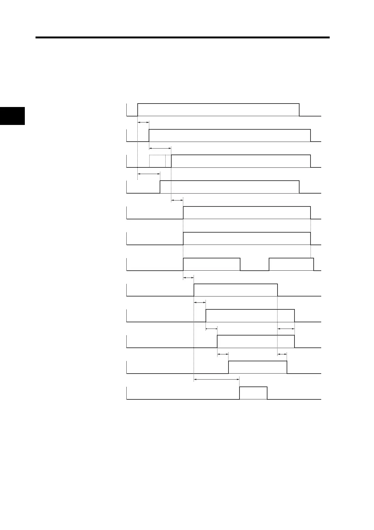
Control Sequence Timing
Power ON operation timing
*1. Servo Ready (READY) turns ON and returns a response when these conditions are met: MPU initialization is
completed, main power is established, no alarms exist, MECHATROLINK-II communications are established, and
the servo is synchronized.
*2. Once the internal control power is established, the protective function starts working about 1.5 s after the CPU starts
initializing itself.
Be sure that the input signals, in particular the Emergency Stop (STOP) and Drive Prohibit (POT/NOT) inputs are
settled before the protective function starts working.
ON
OFF
ON
OFF
ON
OFF
ON
OFF
ON
OFF
ON
OFF
ON
OFF
ON
OFF
ON
OFF
ON
OFF
ON
OFF
ON
OFF
Pn06A
Approx. 10 ms after the main circuit power is
turned ON after initialization is completed.
Alarm Output
(ALM)
Positioning Completed
Output (INP)
Brake Interlock Output
(BKIR)
RUN Command Input
(RUN)
Approx. 2 s
Approx. 100 to 300 ms
Approx. 2 ms
Approx. 2 ms
100 ms min.
0 ms min.
0 ms min.
1 to 5 ms
Approx. 40 ms
Dynamic brake
Servomotor
power supply
Servomotor position, speed,
or torque input
Control power supply
(L1C, L2C)
Inter
nal control power supply
MPU initialization completed
Main circuit power supply
(L1, L2, L3)
Servo Ready Output
(READY)*1
Initialize*2

 Loading...


