1-3
1-3 Names of Parts and Functions
1
Features and System Configuration
1-3 Names of Parts and Functions
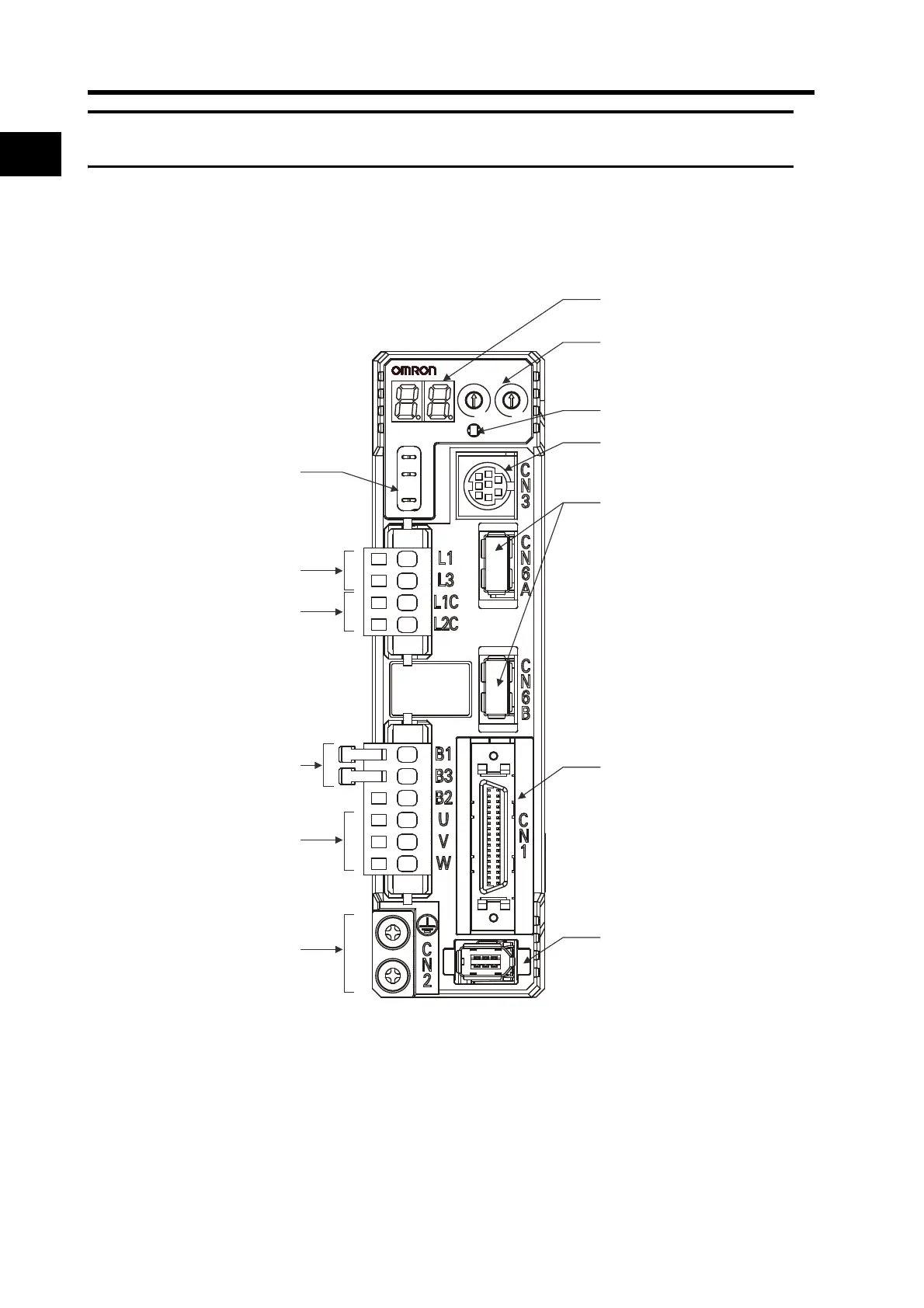
Servo Drive Part Names
Display area
MECHATROLINK-II
communications connector
(
CN6A
,
CN6B
)
Analog monitor check pins
(
SP
,
IM
,
G
)
Servomotor connection terminals
(U, V, W)
Control-circuit power terminals
(L1C, L2C)
Main-circuit power terminals
(L1, L2, L3)
External Regeneration Resistor
connection terminals
(B1, B2, B3)
Protective ground terminals
Control I/O connector (CN1)
RS-232
communications connector
(
CN3
)
Encoder connector (CN2)
MECHATROLINK-II
communications
status LED indicator
Rotary switches
G
IM
SP
COM
X10
3
2
1
0
ADR
AC SERVO DRIVE
X1
6
7
8
9
0
1
2
3
4
5

 Loading...


