© Koninklijke Philips Electronics N.V. 2006. All rights reserved.
User manual Rev. 01 — 12 January 2006 89
Philips Semiconductors
UM10161
Volume 1 Chapter 9: UART0
The UART0 RLS interrupt (U0IIR[3:1] = 011) is the highest priority interrupt and is set
whenever any one of four error conditions occur on the UART0 Rx input: overrun error
(OE), parity error (PE), framing error (FE) and break interrupt (BI). The UART0 Rx error
condition that set the interrupt can be observed via U0LSR[4:1]. The interrupt is cleared
upon an U0LSR read.
The UART0 RDA interrupt (U0IIR[3:1] = 010) shares the second level priority with the CTI
interrupt (U0IIR[3:1] = 110). The RDA is activated when the UART0 Rx FIFO reaches the
trigger level defined in U0FCR[7:6] and is reset when the UART0 Rx FIFO depth falls
below the trigger level. When the RDA interrupt goes active, the CPU can read a block of
data defined by the trigger level.
The CTI interrupt (U0IIR[3:1] = 110) is a second level interrupt and is set when the UART0
Rx FIFO contains at least one character and no UART0 Rx FIFO activity has occurred in
3.5 to 4.5 character times. Any UART0 Rx FIFO activity (read or write of UART0 RSR) will
clear the interrupt. This interrupt is intended to flush the UART0 RBR after a message has
been received that is not a multiple of the trigger level size. For example, if a peripheral
wished to send a 105 character message and the trigger level was 10 characters, the CPU
would receive 10 RDA interrupts resulting in the transfer of 100 characters and 1 to 5 CTI
interrupts (depending on the service routine) resulting in the transfer of the remaining 5
characters.
[1] Values "0000", “0011”, “0101”, “0111”, “1000”, “1001”, “1010”, “1011”,”1101”,”1110”,”1111” are reserved.
[2] For details see Section 9.3.10 “
UART0 Line Status Register (U0LSR - 0xE000 C014, Read Only)”
[3] For details see Section 9.3.1 “UART0 Receiver Buffer register (U0RBR - 0xE000 C000, when DLAB = 0,
Read Only)”
[4] For details see Section 9.3.7 “UART0 Interrupt Identification Register (U0IIR - 0xE000 C008, Read Only)”
and Section 9.3.2 “
UART0 Transmit Holding Register (U0THR - 0xE000 C000, when DLAB = 0, Write
Only)”
The UART0 THRE interrupt (U0IIR[3:1] = 001) is a third level interrupt and is activated
when the UART0 THR FIFO is empty provided certain initialization conditions have been
met. These initialization conditions are intended to give the UART0 THR FIFO a chance to
fill up with data to eliminate many THRE interrupts from occurring at system start-up. The
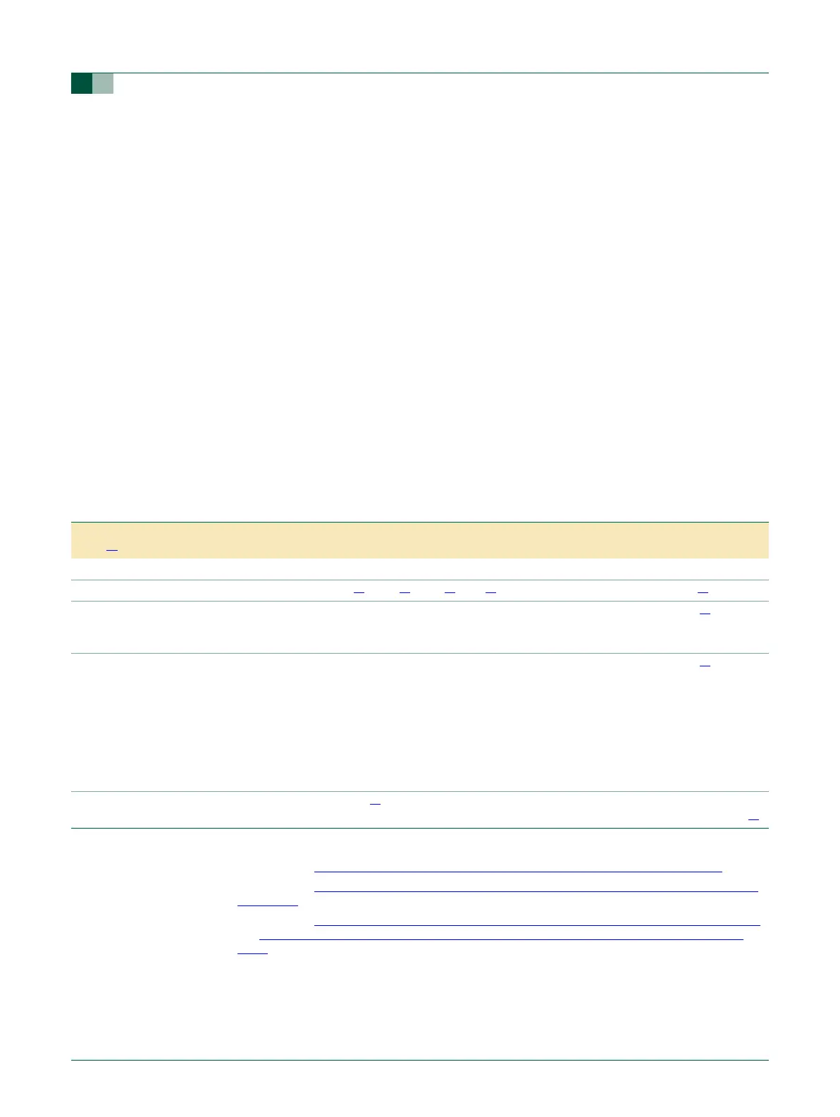
Table 90: UART0 interrupt handling
U0IIR[3:0]
value
[1]
Priority Interrupt Type Interrupt Source Interrupt Reset
0001 - None None -
0110 Highest RX Line Status / Error OE
[2]
or PE
[2]
or FE
[2]
or BI
[2]
U0LSR Read
[2]
0100 Second RX Data Available Rx data available or trigger level reached in FIFO
(U0FCR0=1)
U0RBR Read
[3]
or
UART0 FIFO drops
below trigger level
1100 Second Character Time-out
indication
Minimum of one character in the Rx FIFO and no
character input or removed during a time period
depending on how many characters are in FIFO
and what the trigger level is set at (3.5 to 4.5
character times).
The exact time will be:
[(word length) × 7
− 2] × 8 + [(trigger level −
number of characters) × 8 + 1] RCLKs
U0RBR Read
[3]
0010 Third THRE THRE
[2]
U0IIR Read (if source of
interrupt) or THR write
[4]