User’s Manual of IGS-4215-16T2S
4.5.14 VLAN Setting Example:
- Separate VLANs
- 802.1Q VLAN Trunk
4.5.14.1 Two Separate 802.1Q VLANs
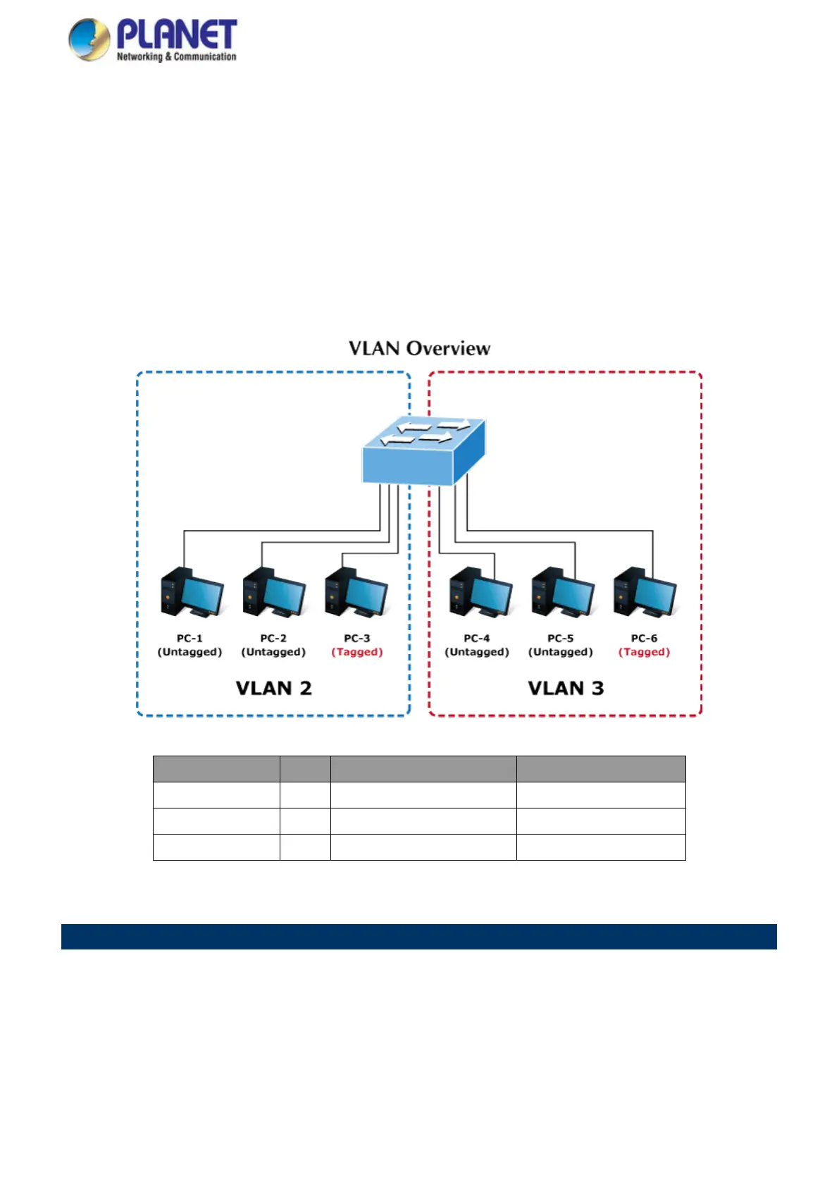
The diagram shows how the Industrial Managed Switch handles Tagged and Untagged traffic flow for two VLANs. VLAN Group
2 and VLAN Group 3 are separated VLANs. Each VLAN isolates network traffic so only members of the VLAN receive traffic
from the same VLAN members. The screen in Figure 4-5-20 appears and Table 4-5-2 describes the port configuration of the
Industrial Managed Switches.
Figure 4-5-20: Two Separate VLAN Diagrams
VLAN Group VID Untagged Members Tagged Members
VLAN Group 1 1 Port-7~Port-8 N/A
VLAN Group 2 2 Port-1,Port-2 Port-3
VLAN Group 3 3 Port-4,Port-5 Port-6
Table 4-5-2: VLAN and Port Configuration
The scenario is described as follows:
Untagged packet entering VLAN 2
1. While [PC-1] transmits an untagged packet entering Port-1, the Industrial Managed Switch will tag it with a VLAN
Tag=2. [PC-2] and [PC-3] will receive the packet through Port-2 and Port-3.
2. [PC-4], [PC-5] and [PC-6] receive no packet.
3. While the packet leaves Port-2, it will be stripped away its tag becoming an untagged packet.
4. While the packet leaves Port-3, it will keep as a tagged packet with VLAN Tag=2.
 Loading...