Chapter F - ADJUSTMENTS
Planmeca Compact i F-21
ELECTRICAL ADJUSTMENTS
Technical Manual
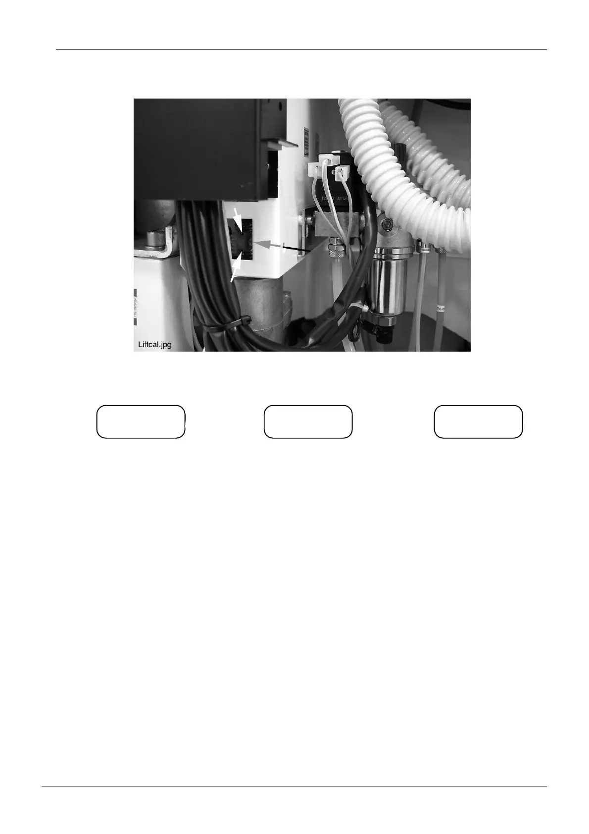
d) Loosen the two M3x6 DIN 916 screws holding the cog wheel of the sensor in position.
e) Rotate the axle of the sensor with a screwdriver until the two horizontal lines on the display
are in line.
f) Tighten the two M3x6 DIN 916 screws to secure the cog wheel into position.
g) Drive the lifting adapter past the calibration mark a couple of times to ensure that the sensor
is now calibrated correctly.
h) Exit service mode.
L– _ L– L– –
The sensor presumes the lifting
adapter to be at a too low position.
Rotate the axle counterclockwise
(seen from the axle).
The sensor presumes the lifting
adapter to be at a too high position.
Rotate the axle clockwise (seen from
the axle).
The sensor is calibrated
correctly.
–