Chapter G - PARTS REPLACEMENT & REPAIR
Planmeca Compact i G-27
MOTORS REPLACEMENT
Technical Manual
6 MOTORS REPLACEMENT
6.1 Replacing backrest motor
a) In the case that the motor is somewhat operational, drive the backrest to the position approx.
20° above the horizontal position.
b) Remove the backrest and seat upholsteries as described in section 2 “UPHOLSTERIES
REPLACEMENT” on page G-3.
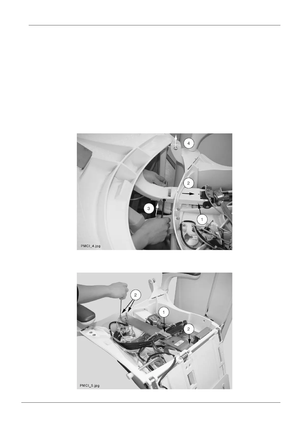
c) Unscrew the attachment screw of the pushing rod cover (1) and slide the cover towards the
backrest motor (2). Lift the backrest so that you can push the pushing rod pivot to away from
position (3). Unscrew backrest joint pivot attachment screws using the 4mm Allen key and
push the backrest joint pivots away from the joints (4). Remove the backrest.
d) Open the cable clamp located on the upholstery support plate (1). Remove the upholstery
support plate by unscrewing the three M6x10 DIN 912 screws (2).