Chapter C - SERVICE MODE
C-4 Planmeca Compact i
GENERAL ABOUT THE SERVICE MODE
Technical Manual
1.5 Service mode functions short-form
The following pages list all available service modes as short-form tables. For detailed descrip-
tions of the service modes, please refer to pages indicated in the right column.
The service modes are grouped according to functions into individual tables.
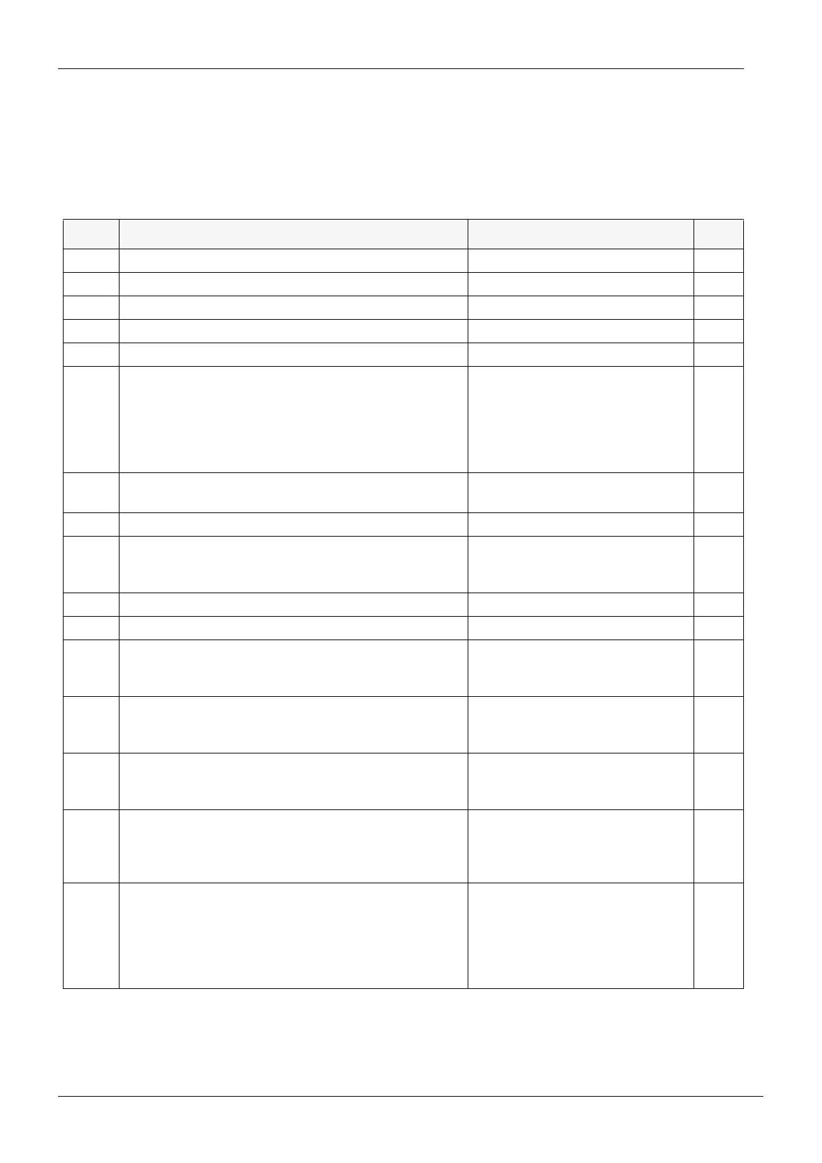
Table 1: MAIN control system related service modes
MODE SERVICE MODE FUNCTION DISPLAY/RANGE page
n.0 Disable programming and limit micromotor speed 0 - 15 (default = 0) C-17
n 1 Show software version on MCB n.nn.n C-18
n 2 Show internal unregulated operating voltage 33.0VDC (±15%), 28.0...38.0 VDC C-18
n 3 Show output current of IPS 0.00 - 7.00 A C-18
n 4 Show output voltage of IPS 00.0 - 33.0 VDC C-18
n 5 Show scaler electronics ID-code 0 = no scaler electronics installed
1 = Amdent
2 = EMS
3 = Satelec
6 = Newtron
4, 5, 7 = reserved
C-19
n 6 Show service door switch signal 0 = door closed
1 = door open
C-19
n 7 Show mains frequency nn.n Hz (cycles/second) C-19
n 8 Show (optional) assistant syringe hose ID - = no hose connected
0 = not a syringe
nn = syringe ID code
C-19
n 9 Show (optional) assistant syringe hose sense signal 0 - 255 C-19
n 10 Show MCB heatsink temperature nn °C (or °F) C-19
n.11 Enable (optional) water heater 1 = enabled (heating on)
- = enabling (10 second delay)
0 = disabled (no heating, default)
C-20
n.12 Set main air valve operation 1 = always on
A = automatic (default)
0 = always off
C-20
n.13 Set main water valve operation 1 = always on
A = automatic (default)
0 = always off
C-20
n.14 Disable automatic functions in S-position 0 = no water to cup or cuspidor
1 = flush cuspidor only
2 = fill cup only
3 = fill cup, flush bowl (default)
C-20
n.15 Disable error messages 0 = no error messages are dis-
played
1 = error messages will show
(default)
2 = error messages relating con-
sole arm are not displayed
C-20