Chapter H - FOOT CONTROL
H-8 Planmeca Compact i
ADJUSTMENTS
Technical Manual
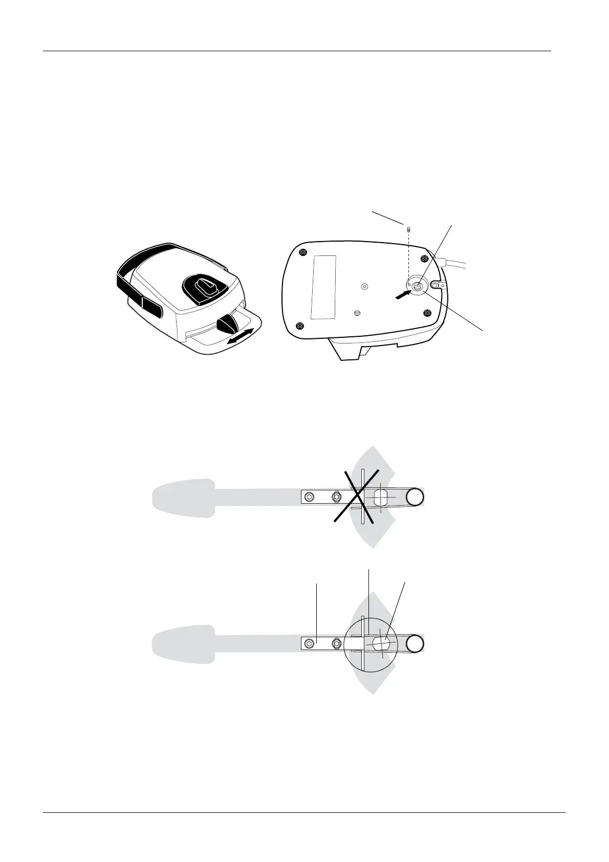
2.2 Eliminating sideways play of the foot control pedal
a) Remove the foot control cover as described in section “Removing foot control cover” on page
H-1.
b) Remove the foot control PCB as described in section “Replacing foot control PCB” on page
H-3.
c) Loosen the M3x4 DIN 916 locking screw on the underside of the foot control and loosen the
locking plate half a turn.
d) Eliminate the horizontal play of the pedal by slightly turning the adjusting rod. When making
the adjustment, ensure that the pedal centering spring touches the adjusting rod and the
centering plate on both sides as shown below.
e) Tighten the locking plate but make sure that the adjusting rod does not move when doing this.
f) Tighten the M3x4 DIN 916 locking screw on the underside of the foot control.
g) Reassemble the foot control in reverse order.
h) Calibrate the foot control as described in section “Calibrating foot control” on page H-15.
adjpedalplay.eps
The sideways play
must be eliminated.
M3x4 DIN 916
Adjusting rod
Locking plate
Adjpedal0199.eps
Centering plate Adjusting rod
Pedal centering spring
WRONG
CORRECT