Chapter G - PARTS REPLACEMENT & REPAIR
G-34 Planmeca Compact i
MOTORS REPLACEMENT
Technical Manual
6.2 Replacing chair lift motor
WARNING
Care must be taken when replacing the chair lift motor. Removing parts of the
lifting assembly may enable the patient chair to fall causing a dangerous
situation and/or damage to the equipment. The downward movement of the
chair must be eliminated before the motor is detached.
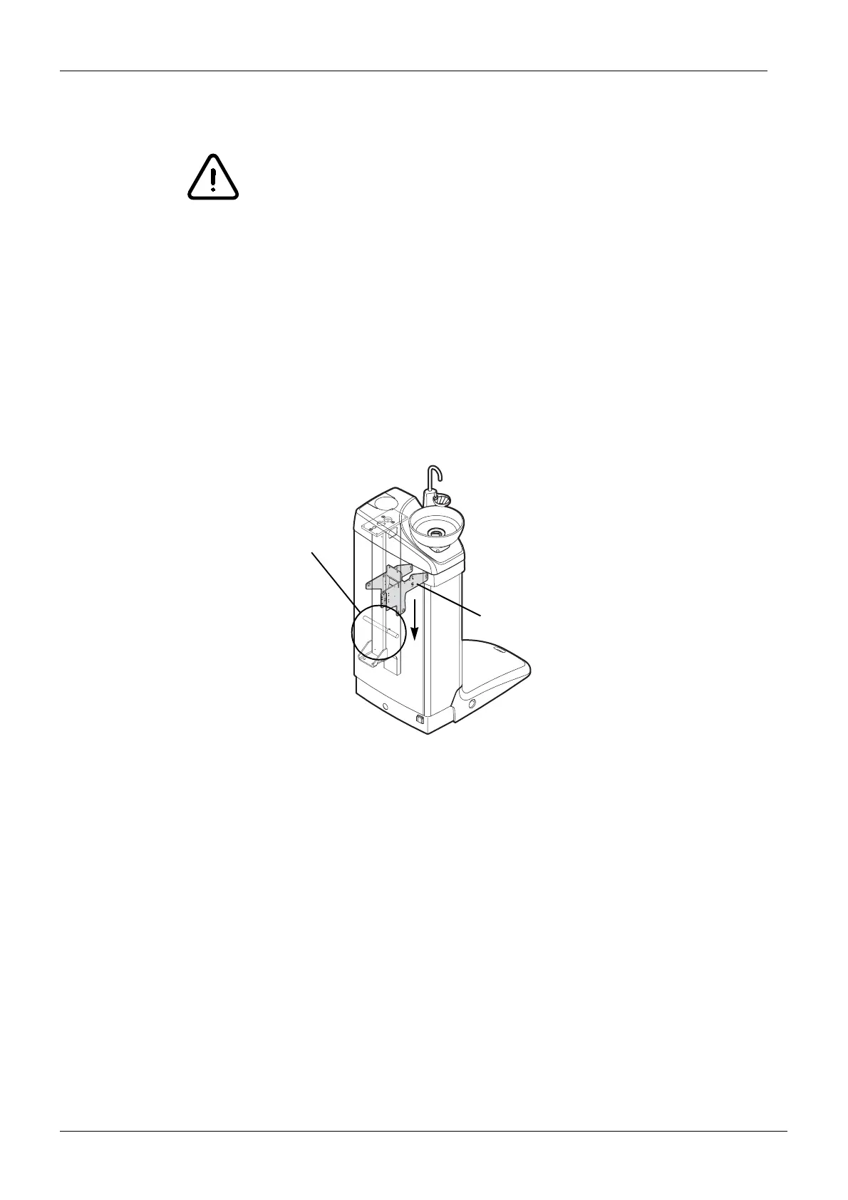
a) In the case that the motor is somewhat operational, drive the patient chair upwards until you
gain access to the opening on the lifting column. Insert a robust steel bar through the lifting
column. Carefully drive the chair downwards until the steel bar supports the lifting adapter
(and the chair).
If the motor is completely jammed, position a robust box etc. under the patient chair to
eliminate the downward movement of the chair.
NOTE Ensure that the steel bar supports the whole weight of the patient chair by try-
ing to pull out the bar. The steel bar must not move.
b) Remove the separator tank.
c) Lift aside the magnetic valve/pressure regulator assembly.
d) Remove the cuspidor cover.
e) Remove all the necessary cable ties relating to the Lift motor cable or the Lift motor
potentiometer cable.
f) Remove the lower cable guide by unscrewing the three M4x8 DIN 912 screws.
g) Remove the cover of the electronics control box.
h) Loosen the four screws that are holding the electronics control box in position and lift the box
aside to gain access to the lift motor.
i) Disconnect the Lift motor potentiometer cable from the connector P24 (Lift pot) on the Main
control PCB.
j) Disconnect the Lift motor cable from the connector P23 (Lift motor).
Insert the steel bar
Drive carefully downwards until
the bar stops the movement