Chapter H - FOOT CONTROL
Planmeca Compact i H-7
ADJUSTMENTS
Technical Manual
2ADJUSTMENTS
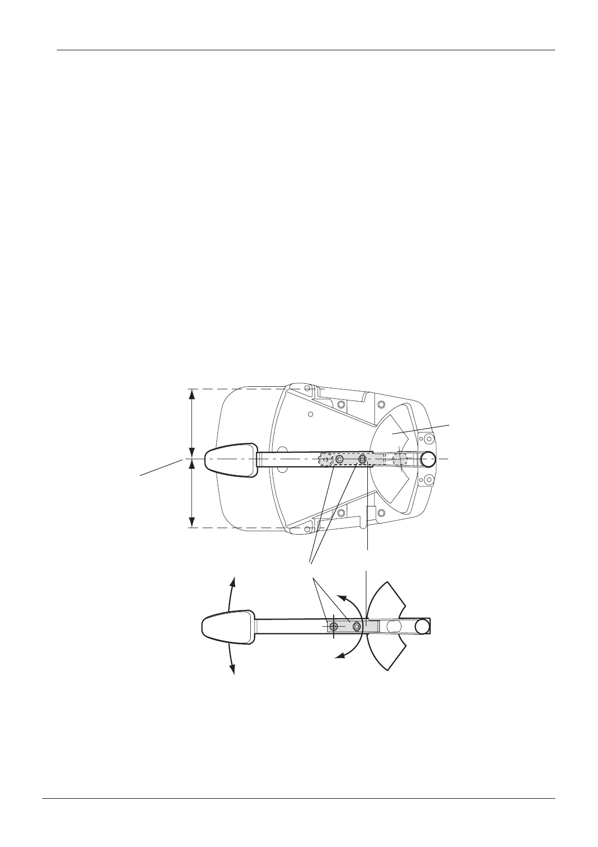
2.1 Centering foot control pedal
NOTE The pedal of the new foot control model is also centered when the sector plate
is calibrated, see section “Calibrating the sector plate and adjusting the angle
of the foot control pedal (new foot control model, from serial number 826740)”
on page H-11.
a) Remove the foot control cover as described in section “Removing foot control cover” on page
H-1.
b) Remove the foot control PCB as described in section “Replacing foot control PCB” on page
H-3.
c) Loosen the two screws which hold the pedal centering plate in position.
d) By adjusting the position of the pedal centering plate, center the foot control pedal so that it is
positioned exactly in the middle of the foot control casting (A=B).
e) Tighten the two pedal centering plate screws.
f) Reassemble the foot control in reverse order.
g) Calibrate the foot control as described in section “Calibrating foot control” on page H-15.
pedal0199.eps
A
B
A=B
Sector plate
Pedal centering plate
Screws
Axis of the
foot control pedal