Chapter G - PARTS REPLACEMENT & REPAIR
G-42 Planmeca Compact i
OTHER PARTS REPLACEMENT
Technical Manual
9 OTHER PARTS REPLACEMENT
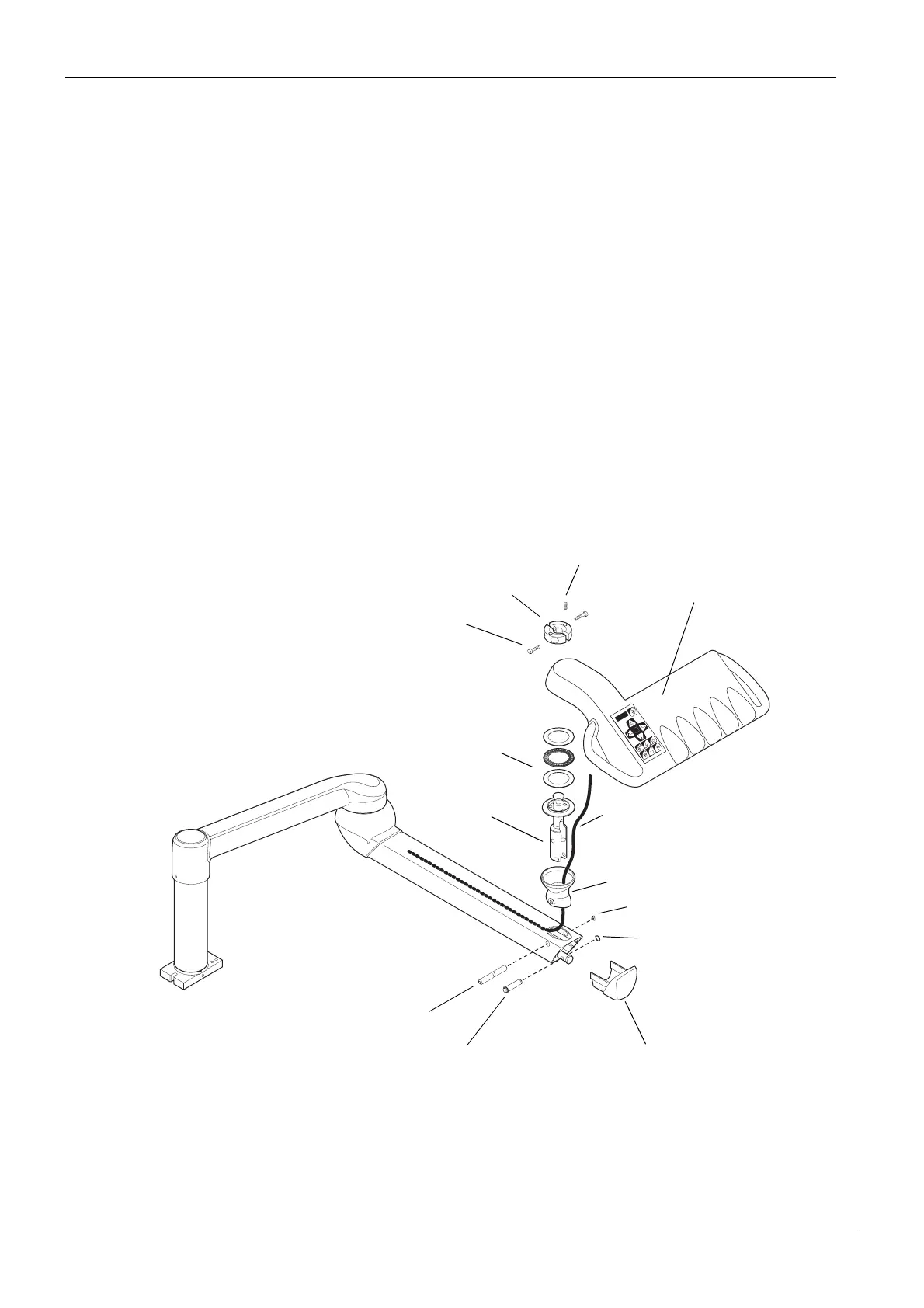
9.1 Detaching the instrument console from the OP delivery arm
a) Remove all the instrument hoses and the instrument arms from the instrument console.
b) Disconnect the cables and tubes of the console arm cable from the instrument multiplexer as
described in section 3.2 “Replacing the whole multiplexer” on page G-7.
c) Remove the friction adjuster by unscrewing the two M5x20 DIN 912 and the M6x16 DIN 916
screws and lift off the whole instrument console.
d) Remove the bearing assembly from the lower joint axle.
e) Remove the lifting arm cover.
f) Detach the ø8 DIN 471 locking ring and tap off the lower joint pin (short) with a hammer.
g) Remove the cover plug and tap off the lower joint pin (long).
h) Lift off the lower joint axle and the lower joint cover.
i) Attach the instrument console to the console arm in reverse order.
S
C
D
A
B
888 8
Friction adjuster
M5x20 DIN 912
M6x16 DIN 916
Instrument console
Bearing assembly
Lower joint axle
Lifting arm cover
Locking ring ø8 DIN 471
Lower joint pin (short)
Cover plug
Lower joint pin (long)
Lower joint cover
Console arm cable