Chapter G - PARTS REPLACEMENT & REPAIR
G-26 Planmeca Compact i
ELECTRICAL PARTS REPLACEMENT
Technical Manual
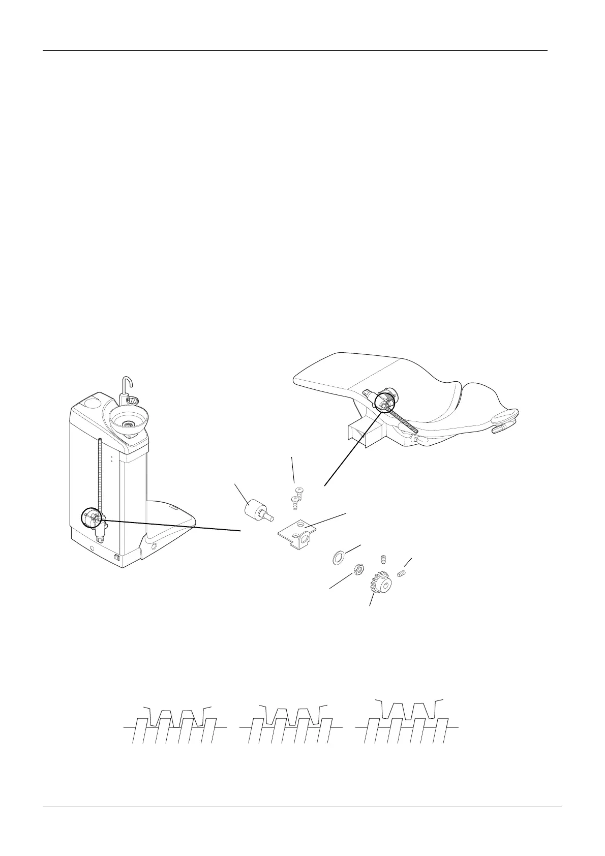
5.8 Replacing position sensors
a) Drive the backrest motor or the chair lift motor to the sensor calibration position (refer to
section 2.1 “Calibrating backrest motor position sensor” on page F-18 or 2.2 “Calibrating lift
motor position sensor” on page F-20 respectively). Do the driving in the normal mode (not in
the service mode).
b) Disconnect the position sensor cable.
c) Loosen the two M4x4 DIN 916 screws and remove the cog wheel.
d) Remove the position sensor by unscrewing the nut.
e) Assemble the new position sensor in reverse order.
NOTE Never try to force the position sensor into the cog wheel, as it might cause the
position sensor to break.
NOTE Care must be taken when assembling the position sensor for positioning the
cog wheel correctly compared to the threaded axle of the motor (see illustra-
tion below).
f) Calibrate the new position sensor as described in section 2.1 “Calibrating backrest motor
position sensor” on page F-18 or in 2.2 “Calibrating lift motor position sensor” on page F-20
section respectively.
WRONG
WRONG
CORRECT
Position sensor
M5x12 DIN 7500
Position sensor plate
Washer
Nut
M4x4 DIN 916
Cog wheel
Cog wheel
Threaded axle
of the motor
Cog wheel too close to the threaded axle
of the motor. The eccentricity of the axle
damages the position sensor.
Cog wheel too far from the threaded axle of
the motor. The eccentricity of the axle causes
the cog wheel to slip and loose position.