Chapter H - FOOT CONTROL
Planmeca Compact i H-3
PARTS REPLACEMENT & REPAIR
Technical Manual
1.3 Replacing foot control PCB
a) Remove the foot control cover as described in section “Removing foot control cover” on page
H-1.
b) Remove the chair control assembly as described in section “Replacing chair control springs”
on page H-2.
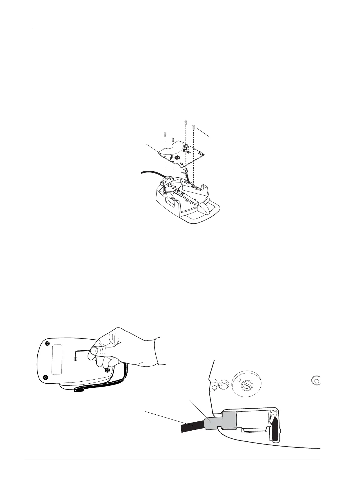
c) Detach the foot control cable from the connector P1 on the foot control PCB.
d) Unscrew the four M4x10 DIN 7991 screws and remove the foot control PCB.
e) Install the new foot control PCB in reverse order.
1.4 Replacing foot control cable
a) Disconnect the foot control cable from the cuspidor by pushing the cable locker and pulling
out the cable.
b) Remove the foot control cover as described in section “Removing foot control cover” on page
H-1.
c) Remove the bottom plate by unscrewing the center screw as shown.
d) Detach the foot control cable from the connector P1 on the foot control PCB.
e) Lift the strain reliefer upwards and pull the foot control cable out.
f) Install the new foot control cable in reverse order.
fcntrlpcb0199.eps
M4x10 DIN 7991
Foot control PCB
Foot control cable
cable2.eps
Strain reliefer