Chapter H - FOOT CONTROL
H-2 Planmeca Compact i
PARTS REPLACEMENT & REPAIR
Technical Manual
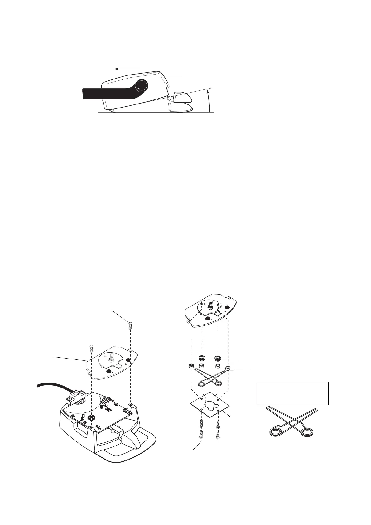
d) Remove the cover assembly by first lifting it upwards at the front and then sliding it backwards
as shown below.
e) Reassemble in reverse order.
1.2 Replacing chair control springs
a) Remove the foot control cover as described in section “Removing foot control cover” on page
H-1.
b) Unscrew the two M4x10 DIN 7991 screws and lift off the chair control assembly.
c) Unscrew the four M4x8 ULS screws and remove the spring support plate.
d) Replace the damaged chair control springs with new ones.
NOTE Always replace both springs.
NOTE The angle between the spring legs must be closing. If not, bend the spring legs
slightly towards each other.
NOTE The springs must be positioned in a way, that they can easily overlap each
other (one bends upwards, the other bends downwards).
e) Reassemble in reverse order.
cove0199.eps
Cover assembly
(1)
(2)
fcntrlspring0199.eps
M4x10 DIN 7991
M4x8 ULS
Spring support
plate
Chair control
springs
Spring support
Spacer
NOTE THE ORIENTATION
OF THE SPRINGS: THEY MUST
EASILY OVERLAP EACH OTHER.
Chair control
assembly