Chapter G - PARTS REPLACEMENT & REPAIR
G-12 Planmeca Compact i
INSTRUMENT MULTIPLEXER RELATED
Technical Manual
3.4 Replacing multiplexer control membrane
Every multiplexer block, except the syringe (next to the control panel) has a control mem-
brane, which blocks air and water for the instrument (instrument not active).
NOTE Care must be taken to position the new multiplexer control membrane cor-
rectly.
NOTE Carefully tighten the screws equally and crosswise when repositioning the
multiplexer block cover. Using too much force might damage the threads in the
multiplexer block.
a) Perform the pre-replacement preparations described in section 3.1 “Preparations before
instrument multiplexer related replacements” on page G-7.
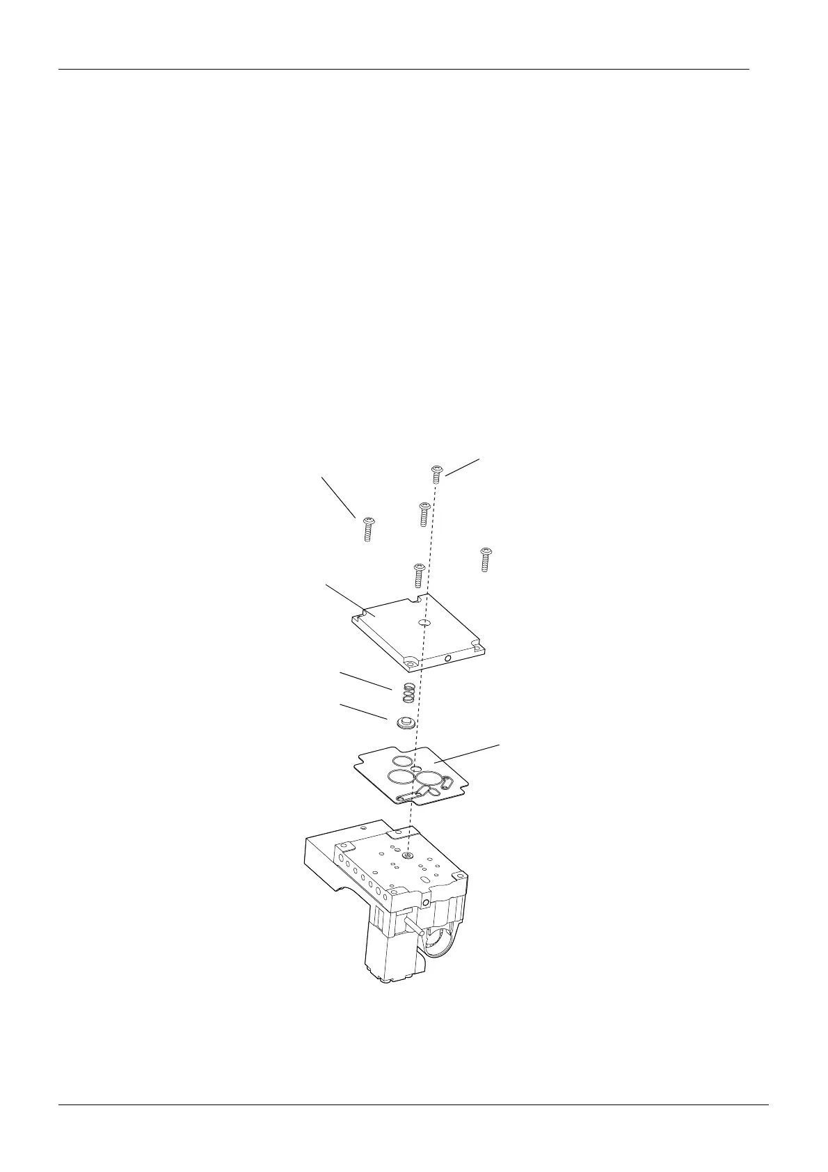
b) Unscrew the four TORX WN1451 3x22 PT screws and one TORX WN1451 3x12 PT screw
from the multiplexer block to be repaired and remove the block cover.
c) Remove the spring and membrane press.
d) Install the new control membrane in reverse order.
TORX WN1451 3x12 PT
TORX WN1451 3x22 PT
Block cover
Multiplexer control
membrane
Spring
Membrane press