Chapter F - ADJUSTMENTS
Planmeca Compact i F-3
MECHANICAL ADJUSTMENTS
Technical Manual
1.3 Adjusting balance of the OP delivery arm
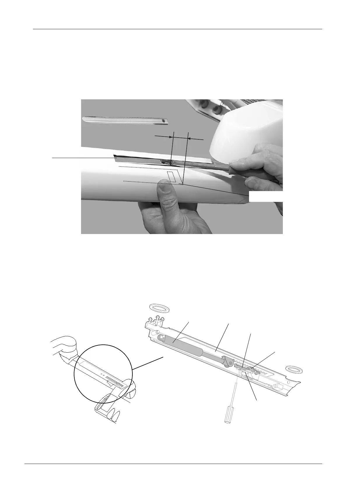
Remove the cable guide plate.
NOTE When replacing the cable guide plate to its position, note that the distance
between the end of the guide and the end of the adjustment plate must be 0-
20mm (0-0.8 in.).
Adjusting the balance
The adjustment plate, which is connected to the gas spring, is held in position with the spring
support. To increase or decrease the tension of the gas spring, the position of the spring sup-
port compared to the adjustment plate must be altered. This is done with the aid of the adjust-
ing hook, which is pushed by a screwdriver (use a robust, round-shaped (not six-edged)
screwdriver with a diameter of 4.5…5.5 mm).
0...20 mm
Wireguide_4.2.eps
Adjustment plate
Cable
guide
plate
Adjustment plateGas spring
Spring support
Adjusting hook
y-spring