Chapter F - ADJUSTMENTS
F-4 Planmeca Compact i
MECHANICAL ADJUSTMENTS
Technical Manual
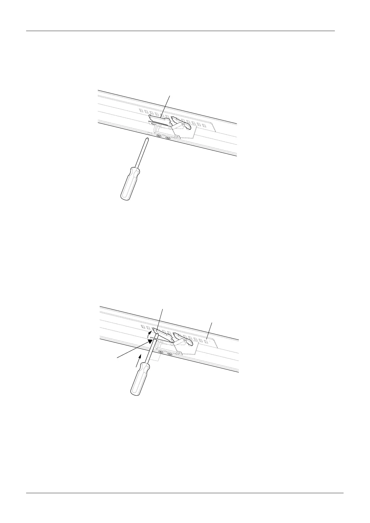
Increasing tension of the gas spring (more load)
I-1) Lower the console arm to its lowest position.
I-2) Insert a screwdriver into the arm (through the opening at the underside of the arm) and
push the adjusting hook (inside the arm) into a groove of the adjustment plate. Make
sure that the screwdriver goes through the hole in the y-spring. Insert the screwdriver
into the arm perpendicularly towards the arm.
NOTE Do not let the screwdriver go through the groove on the adjustment plate to
avoid damaging the tubes above the adjustment plate.
varsikuvaI-1.eps
The spring support is holding the gas spring at the preset ten-
sion. Adjusting hook is hanging freely.
Adjusting hook
varsikuvaI-2.eps
90˚
Adjusting hook goes into a groove of the adjustment plate.
Adjusting hook
Hole in the y-spring
Adjusting plate