Chapter G - PARTS REPLACEMENT & REPAIR
Planmeca Compact i G-25
ELECTRICAL PARTS REPLACEMENT
Technical Manual
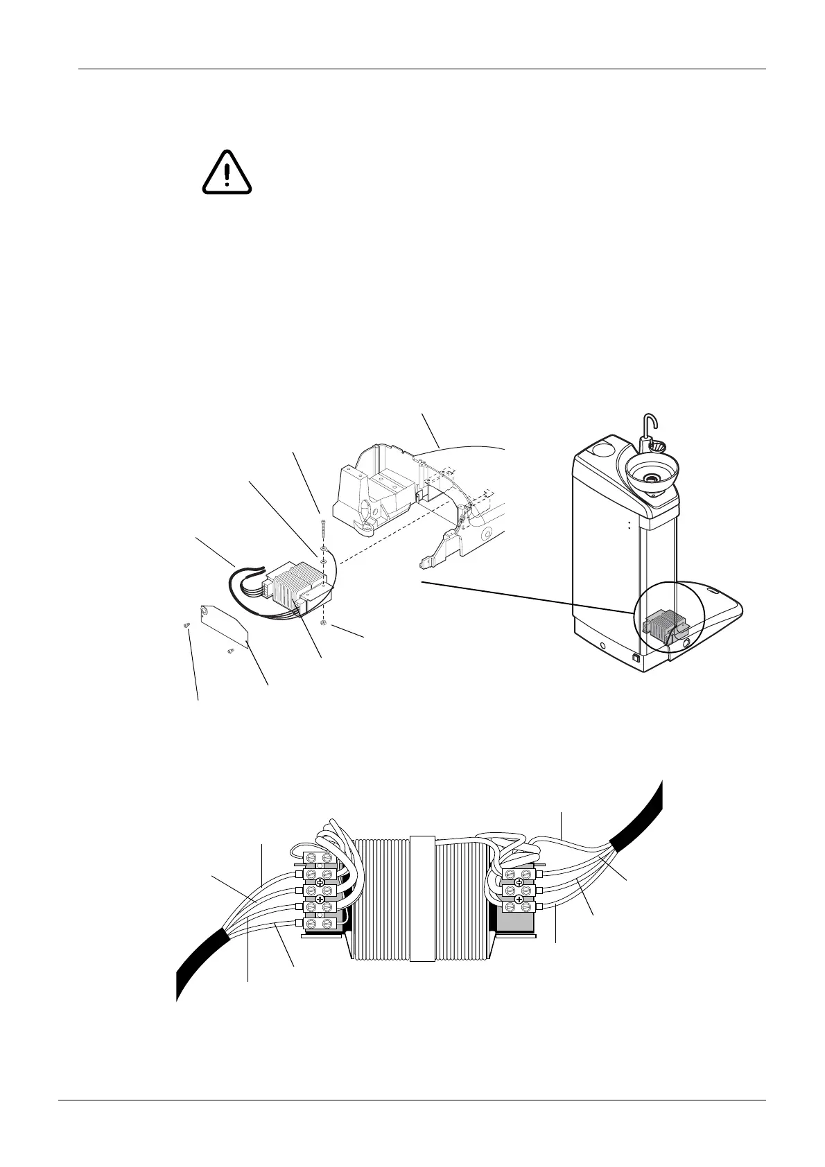
5.7 Replacing transformer
WARNING
The unit must be switched off prior to transformer replacement.
a) Turn off the unit from the mains switch.
b) Unscrew the two M4x6 DIN 912 screws and remove the transformer cover.
c) Pull the transformer out from inside the cuspidor base.
d) Detach the grounding lead of the transformer cable by unscrewing the M6x60 DIN 912 screw.
e) Disconnect all the leads of the transformer cable.
f) Install the new transformer in reverse order.
Cuspidor base
M6x60 DIN 912
ø6.4 DIN 6798
M6 DIN 934
Transformer
M4x6 DIN 912
Transformer cover
Transformer cable
TRANSFORMER CONNECTIONS
PRIMARY LEADS SECONDARY LEADS
YELLOW (230 V~)
RED (115 V~)
BROWN (100 V~)
BLUE (NEUTRAL)
YEL/GRN (CHASSIS GND)
BLUE (24 V~~)
ORANGE (GND)
GREEN (24 V~)